
Monolithic Scintillators With Optical Fiber Read-Out

Inactive Publication Date: 2009-01-29
SIEMENS MEDICAL SOLUTIONS USA INC
View PDF2 Cites 11 Cited by
  • Summary
  • Abstract
  • Description
  • Claims
  • Application Information

AI Technical Summary

Benefits of technology

[0007]A scintillation detector according to an embodiment of the invention features a monolithic scintillation crystal and a plurality of optical fibers coupled to the scintillation crystal. The optical fibers are arranged to convey scintillation light to an optical sensor that is located exterior to the scintillation crystal. Because the optical fibers are extremely small in diameter—in particul

Problems solved by technology

In such systems, the resolution of the system—i.e., the ability to localize the interaction event—was limited by the size and hence “packing” or “clustering” ability of the photosensor elements.
Fabricating pixelated scintillation detectors is, however, relatively labor intensive, and there is a limit to how small the scintillation elements could be made.
Furthermore, the known pixelated gamma detectors typically could be used only to determine the location of gamma interaction with the detector in two dimensions, which gave rise to parallax errors.
More particularly, a conventional two-dimensional measurement of the spatial location of a detected gamma ray absorption event in the scintillating crystal is limited to a two-dimensional point in the X,Y plane of the crystal.

Method used


Image

  • Monolithic Scintillators With Optical Fiber Read-Out
  • Monolithic Scintillators With Optical Fiber Read-Out
  • Monolithic Scintillators With Optical Fiber Read-Out

Examples


embodiment 10

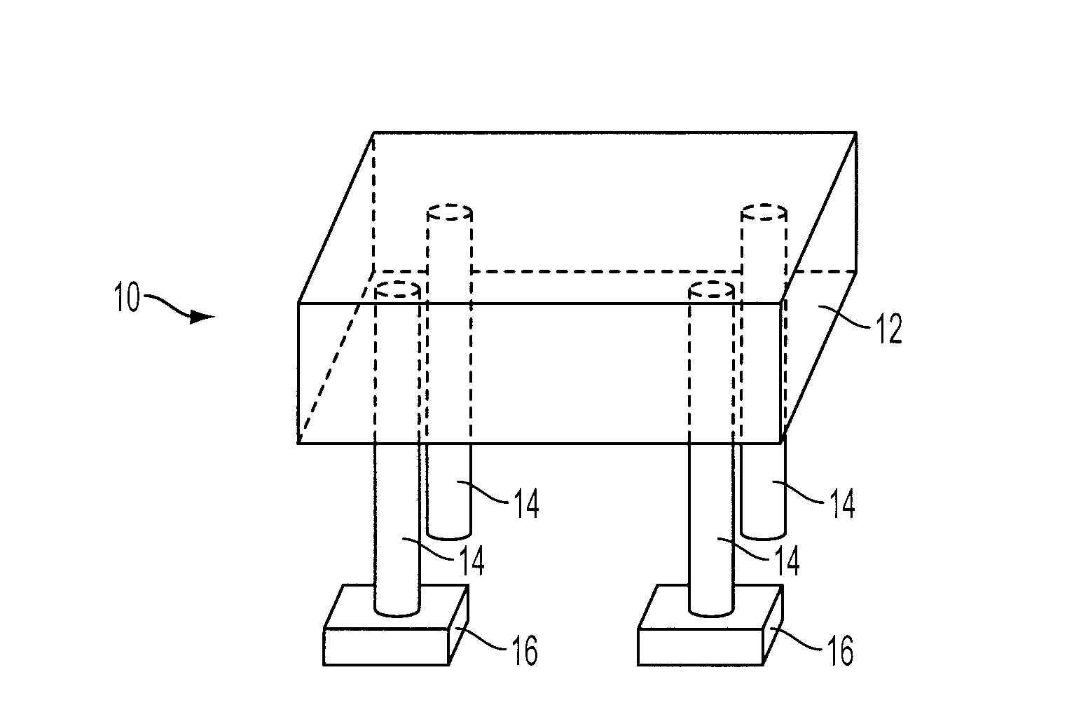
[0016]In the embodiment 10 illustrated in FIG. 1, the optical fibers 14 are coupled to the scintillation crystal 12 by virtue of input end portions of the fibers 14 being embedded within the scintillation crystal 12. In such instance, the embedded input end portions of the optical fibers are suitably unclad or roughened so that light may enter the fibers most easily, whereas the portions of the optical fibers that are exterior to the scintillation crystal 12 are suitably clad so as to promote transmission of light along the fibers to the photosensors 16.

[0017]Furthermore, the end portions of the optical fibers 14 may be embedded by pre-forming cavities using high-temperature materials around which the crystal is grown; alternatively, very small cavities may be formed in the scintillation crystal 12 after it is manufactured, e.g., by laser drilling or mechanical drilling, and the ends of the optical fibers inserted into and fixed within the cavities, e.g., using optically transmissiv...

embodiment 20

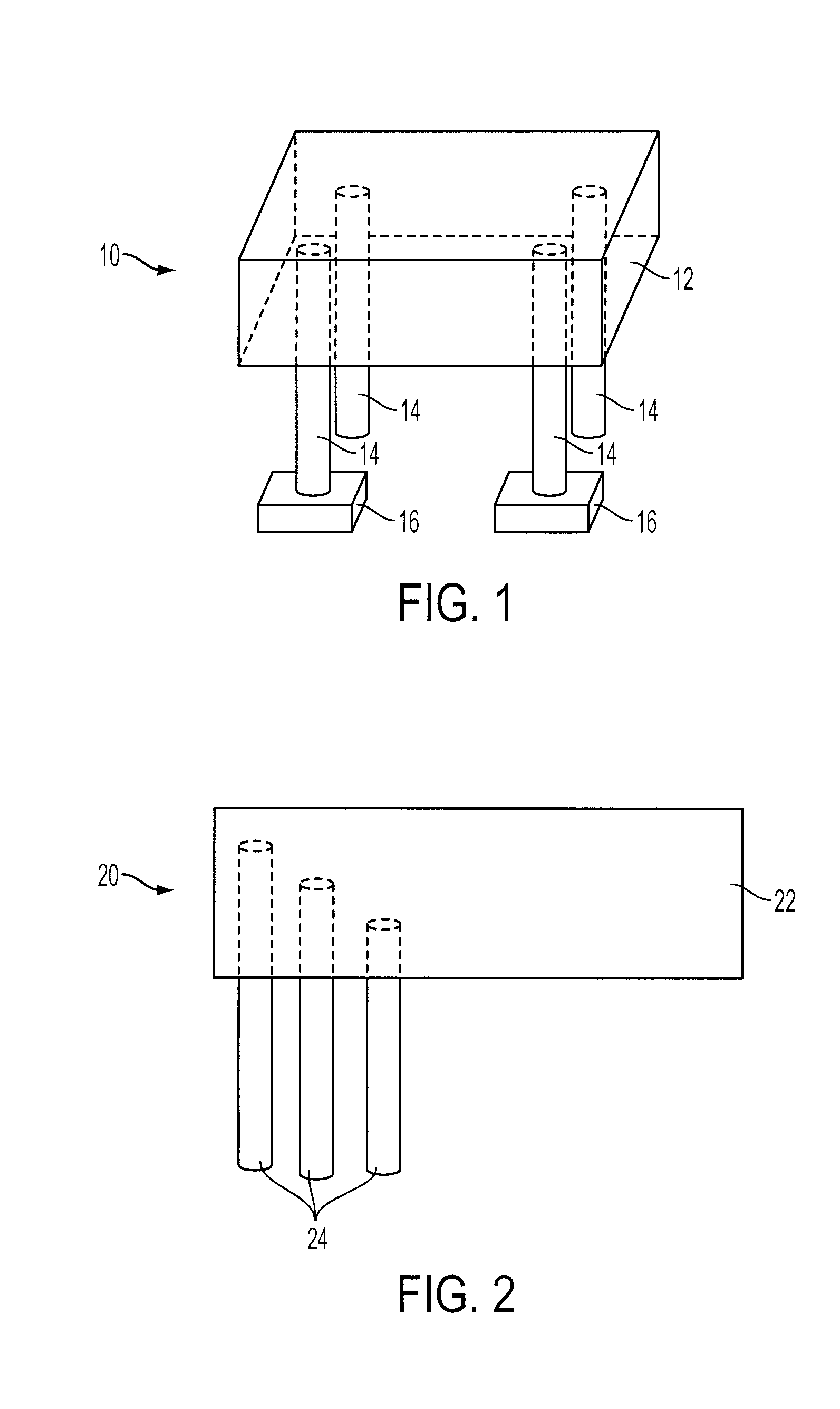
[0020]In another embodiment 20 illustrated in FIG. 2, optical fibers 24, each coupled to a photosensor (not shown), may be embedded within a monolithic scintillation crystal 22. In this embodiment 20, the optical fibers 24 are suitably different lengths, with upper ends (as shown in the Figure) extending into the scintillation crystal 22 to different extents and lower ends (as shown in the Figure) essentially aligned. Alternatively, the optical fibers 24 may all have the same length, but still extend into the scintillation crystal 22 to different extents. By sensing which optical fiber 24 carries the strongest light signal, and knowing the depth of penetration (and, if necessary, the relative X-Y spacing) of the various fibers, one may ascertain the depth of interaction (DOI) information for any given scintillation event. These variant-length optical fibers 24 may constitute a set of fibers that is supplemental to a set of equal-length, equal-depth-of-penetration fibers such as thos...

embodiment 60

[0025]Similarly, in the embodiment 60 illustrated in FIG. 6, the optical fibers 64 are aligned with and coupled in parallel relation to the radiation receiving surfaces of the scintillation crystal 62 instead of being oriented perpendicular to such surfaces as in FIGS. 1-4. In this embodiment, the optical fibers 64 coupled to one surface of the scintillation crystal 62 are orthogonal to the optical fibers 64 coupled to the opposite surface of the scintillation crystal 62. As shown, the fibers coupled to one surface may be coupled to a first common position-sensitive photosensor 66 and the fibers coupled to the other surface may be coupled to a second common position-sensitive photosensor 66. Alternatively, the fibers on one or both surfaces may be bent at a 45° and coupled to a single, common position-sensitive photosensor that is oriented at the corner of the scintillation crystal 62.

[0026]This arrangement of the fibers provides strong capability to differentiate the X-Y position o...


PUM


Abstract

A scintillation detector according to an embodiment of the invention features a monolithic scintillation crystal and a plurality of optical fibers coupled to the scintillation crystal. The optical fibers are arranged to convey scintillation light to an optical sensor that is located exterior to the scintillation crystal. Because the optical fibers are extremely small in diameter, a multiplicity of them can be coupled to the scintillation crystal to provide the extremely high resolution of a pixelated scintillation crystal while the comparative manufacturing simplicity of a monolithic scintillation crystal is maintained. In preferred embodiments, the optical fibers are further arranged so that depth of interaction information can be obtained.

Description

TECHNICAL FIELD[0001]In general, the invention relates to nuclear medical imaging. More particularly, the invention relates to gamma radiation detectors used, for example, in positron emission tomography (PET) scanning.BACKGROUND OF THE INVENTION[0002]In PET imaging, positrons are emitted from a radiopharmaceutically doped organ or tissue mass of interest. The positrons combine with electrons and are annihilated and, in general, two gamma photons which travel in diametrically opposite directions are generated upon that annihilation. Opposing crystal detectors, which each scintillate upon being struck by a gamma photon, are used to detect the emitted gamma photons. By identifying the location of each of two essentially simultaneous gamma interactions as evidenced by two essentially simultaneous scintillation events, a line in space along which the two gamma photons have traveled (a “line of response,” or “LOR”) can be determined. The LORs associated with many million gamma interactio...

Claims


Application Information

Patent Timeline
IPC IPC(8): G01T1/20
CPCG01T1/202G01T1/20
Inventor DOSHI, NIRAJ K.
Owner SIEMENS MEDICAL SOLUTIONS USA INC
Learn More