On-vehicle power supply device

a power supply device and vehicle technology, applied in emergency power supply arrangements, process and machine control, instruments, etc., can solve the problems of inconvenient use, occupying space in the car, users no longer being able to obtain the electric power of the car battery from the cigarette lighter or converted, etc., to achieve simple and reduced circuit design

Inactive Publication Date: 2009-01-29
POWERTECH INDAL
View PDF7 Cites 25 Cited by
  • Summary
  • Abstract
  • Description
  • Claims
  • Application Information

AI Technical Summary

Benefits of technology

[0008]In view of the foregoing shortcoming of the prior art, the inventor of the present invention intended to simultaneously supply AC and DC power isolated from a car battery through a simple and reduced circuit design, so that an output power can isolate noises produced by a car battery when the car battery is charged, and design a plurality of DC power outputs for a flexible application. In the meantime, the present invention further designs a rechargeable battery which is charged when the car supplies electric power, and automatically forms a power supply to allow users to maintain a continuous use of an electronic peripheral device when the car does not supply electric power, so as to achieve the effects of multipurpose, safety, and continuity.

Problems solved by technology

If a user intends to use a DC electronic peripheral device through the car inverter in a car, the user needs to use an AC / DC adapter originally bundled with the DC electronic peripheral device, but such application is inconvenient and occupies space in the car.
In addition, the main issue of the prior art resides on that users cannot obtain a power supply continuously, since the car battery supplies electric power to users only when the car engine is turned on.
If the car engine is turned off, the users no longer can obtain the electric power of car battery from the cigarette lighter or converted by the car inverter.
As a result, the users cannot continue using the electronic peripheral device.

Method used


Image

  • On-vehicle power supply device
  • On-vehicle power supply device
  • On-vehicle power supply device

Examples


Embodiment Construction

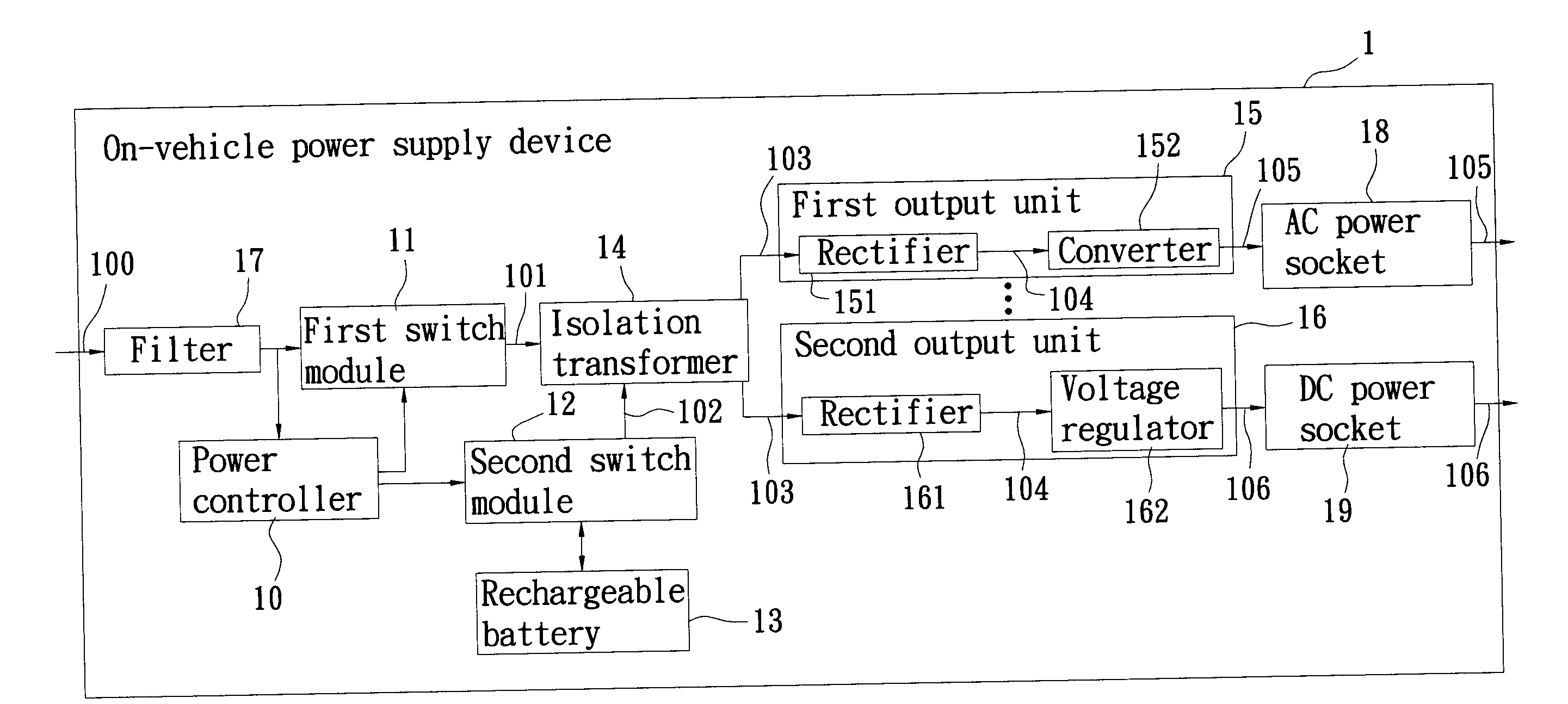
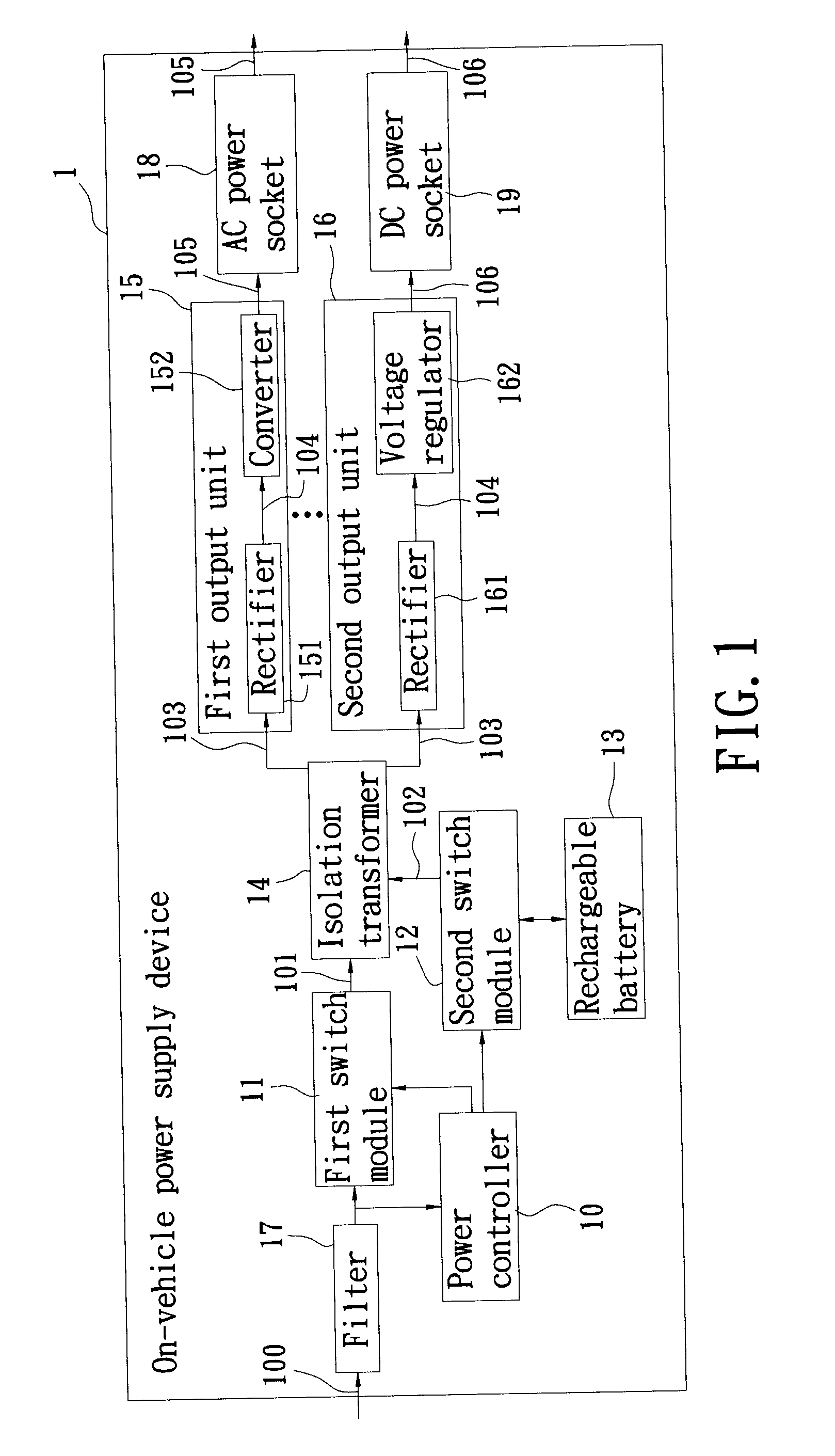
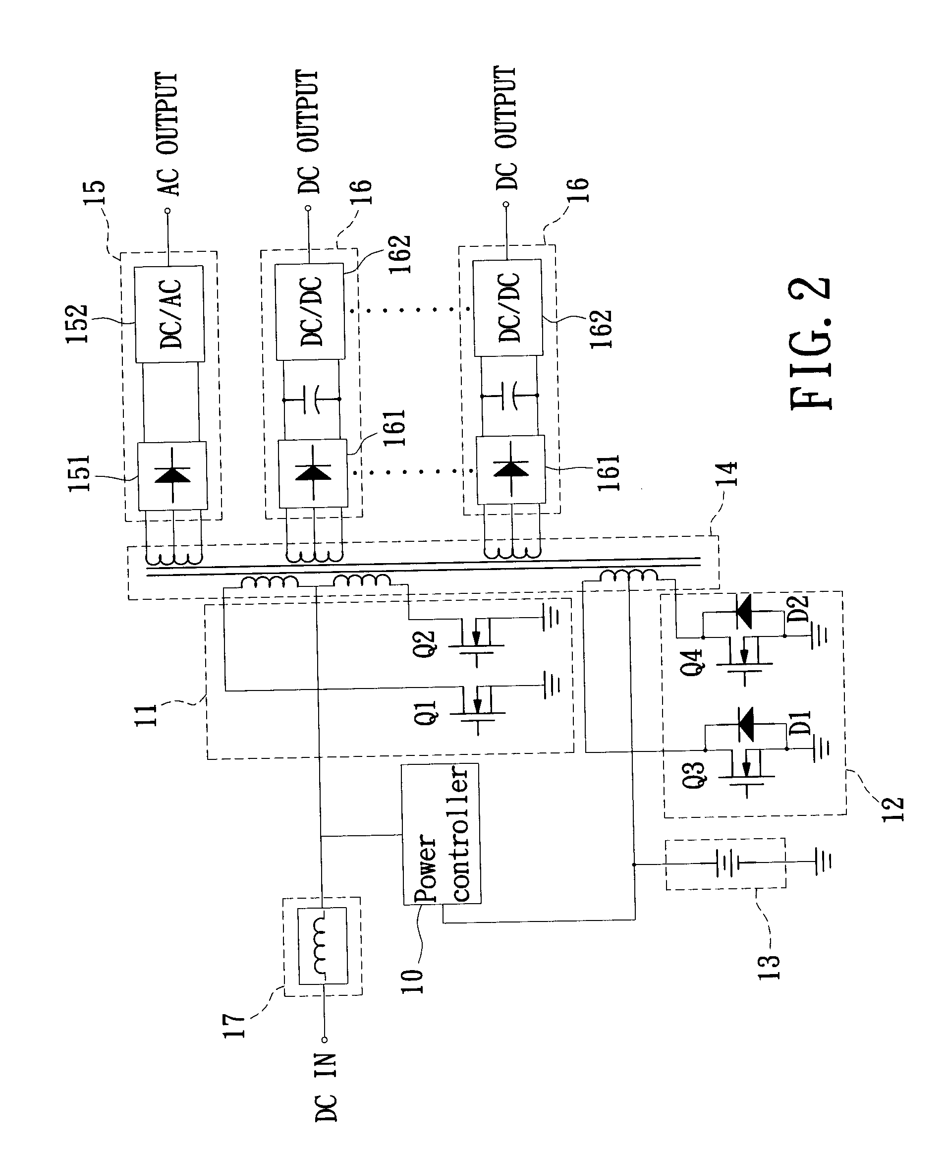
[0014]Referring to FIGS. 1 and 2 for a block diagram and a schematic circuit diagram of an on-vehicle power supply device in accordance with the present invention, the on-vehicle power supply device 1 is installed to a vehicle by an exposing method and connected to a vehicle battery (not shown in the figure) for supplying DC power and AC power to users in a car through various designs of electric power outputs.

[0015]The on-vehicle power supply device 1 of the invention comprises: a power controller 10, a first switch module 11, a second switch module 12, a rechargeable battery 13, an isolation transformer 14, at least one first output unit 15, at least one second output unit 16, a filter 17, at least one AC power socket 18 and at least one DC power socket 19. The rechargeable battery 13 is mainly used for storing and supplying a backup power. In other words, the on-vehicle power supply device 1 not only obtains a DC input power 100 from the vehicle battery, but also obtains a backup...


PUM


Abstract

An on-vehicle power supply device is connected to a vehicle battery with revealing. The on-vehicle power supply device is used for receiving a DC input power supplied by the vehicle battery, and the on-vehicle power supply device induces a plurality of high-frequency voltages through a single isolation transformer at the same time, and then transforms the high-frequency voltages to produce at least one AC output voltage and DC output voltage. In addition, the on-vehicle power supply device further includes a rechargeable battery. The rechargeable battery can be charged when the DC input power is importing. When the DC input power stops importing, the rechargeable battery is used for supplying a backup power to the isolation transformer, and the rechargeable battery keeps producing AC output voltage and DC output voltage. Hence, the present invention can achieve the effects of multipurpose, safety, and continuity.

Description

BACKGROUND OF THE INVENTION[0001]1. Field of the invention[0002]The present invention relates to a power supply device, and more particularly to an on-vehicle power supply device.[0003]2. Description of Related Art[0004]In recent years, technological industries are developed rapidly, and electronic technologies are integrated and applied extensively in many different fields to gain competitive edges and values. As to the automobile industry, more and more automobile electronics are applied and integrated into cars each year. For example, LED related products, multimedia A / V products, monitoring devices and global positioning systems (GPS) are installed in cars. Of course, many technologies also modify their designs to support more on-vehicle electronic products, and thus this business opportunity obviously becomes one of the key factors for the development of electronics in the future.[0005]To integrate or support the electronic peripheral devices, designers and manufacturers need t...

Claims


Application Information

Patent Timeline
Patent Type & Authority Applications(United States)
IPC IPC(8): B60R16/02H02J7/00H02M3/335
CPCH02J9/062H02J9/061
Inventor LEE, YU-LUNG
Owner POWERTECH INDAL
Why Eureka
Try Eureka