Clock frequency dividing circuit

a frequency dividing circuit and frequency dividing technology, applied in the direction of oscillator generators, continuously circulated pulse counters, pulse techniques, etc., can solve the problems of small power consumption and output phase noise of frequency dividing circuits using injection lock techniques, problems in size, cost,

Inactive Publication Date: 2009-01-29
FUJITSU LTD
View PDF2 Cites 9 Cited by
  • Summary
  • Abstract
  • Description
  • Claims
  • Application Information

AI Technical Summary

Problems solved by technology

As a result, timing conditions imposed on clocks used in analog circuits and digital circuits realizing high-speed operation are becoming stricter.
Generally, power consumption and output phase noise of a frequency dividing circuit using the injection lock technique are smaller than those of a frequency dividing circuit using a FF circuit.
However, in the application in relatively low frequencies of less than several GHz, a required clock frequency is less than several GHz, and the use of the injection lock technique requires large values of L and C of the LC oscillator, which poses various problems in terms of size, cost, and the like.
However, in a conventional typical frequency dividing circuit using a FF circuit, it is difficult to reduce power consumption and output phase noise and so on.
A frequency dividing circuit using the injection lock technique, though drawing attention because of its small power consumption and output phase noise, has a problem of insufficient followability with input clocks in a wide frequency range because of its narrow band characteristic.
For example, when a clock output by a PLL is frequency-divided, there arises a problem that the lock range is not wide enough to cover a frequency range of the output clock of the PLL.
Thus, in using the injection lock technique realizing lower power consumption and small output phase noise, widening a lock range is a great problem to be solved for realizing its practical use.
Further, the frequency dividing circuit using the injection lock technique disclosed in the above-mentioned non-patent document has a problem that it is difficult to guarantee a phase relation of four-phase output clocks since the phase relation of the four-phase output clocks depends on an initial internal state and thus is not stable.

Method used


Image

  • Clock frequency dividing circuit
  • Clock frequency dividing circuit
  • Clock frequency dividing circuit

Examples


first embodiment

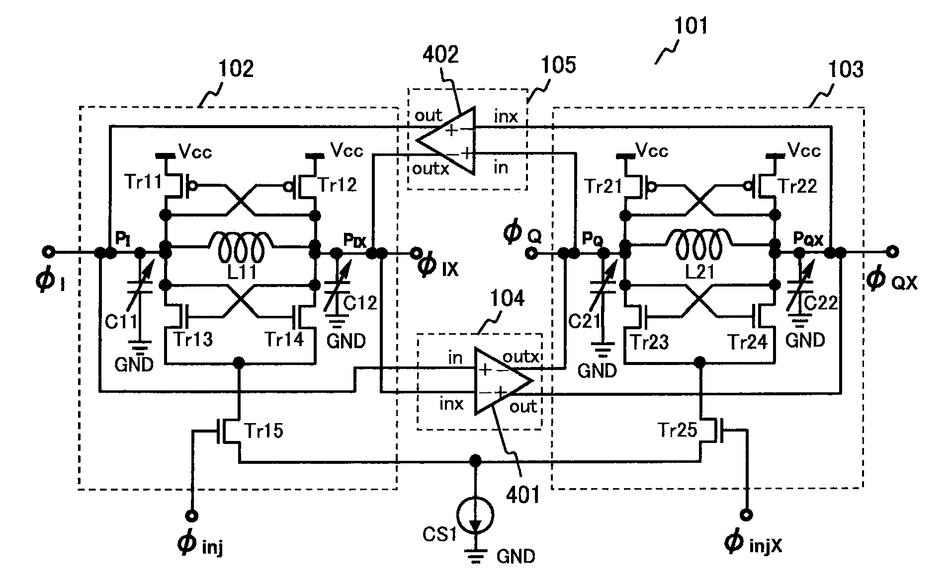
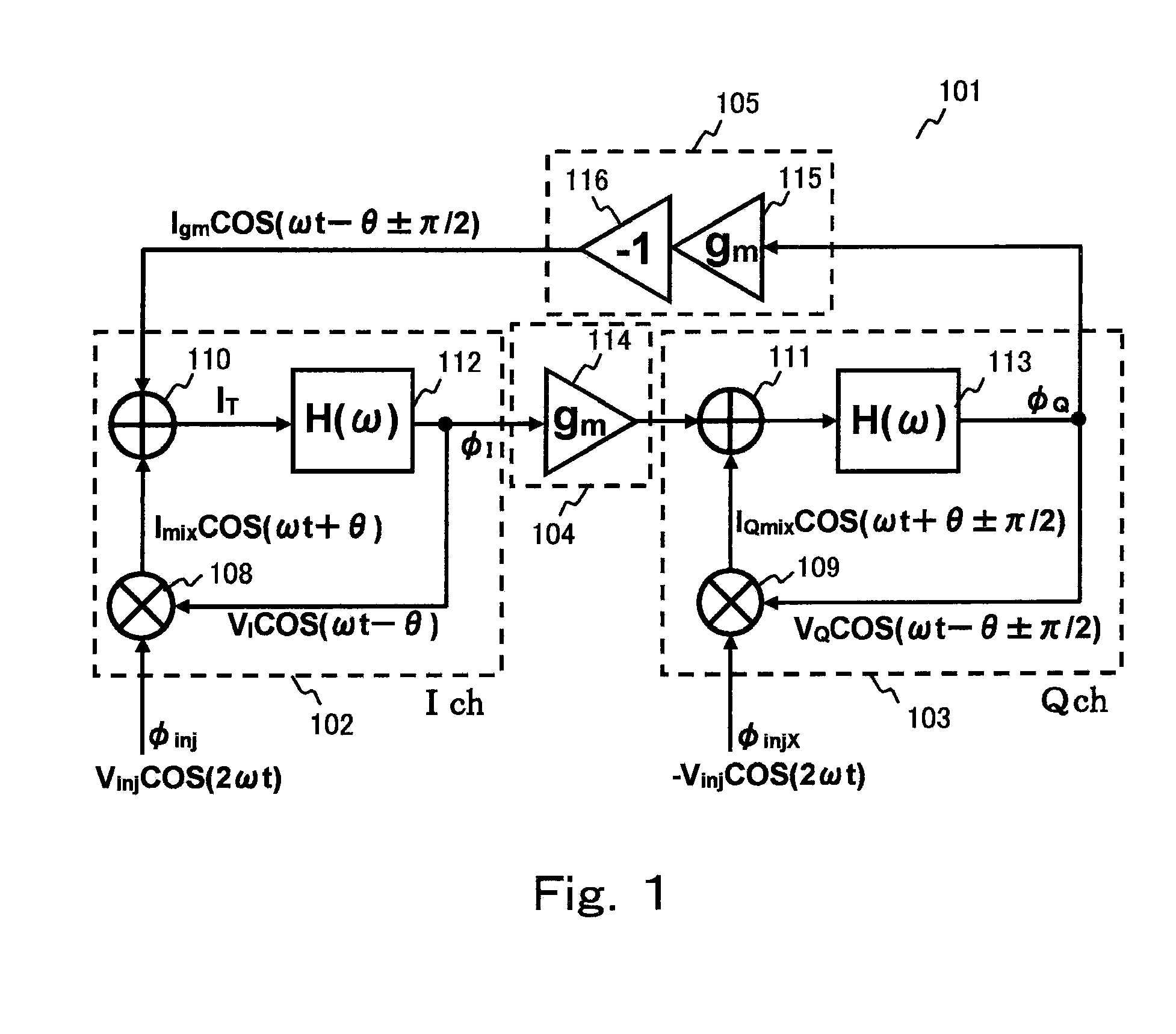
[0029]The first frequency dividing circuit 102 and the second frequency dividing circuit 103 receive two-phase external clocks φinj and φinjx each with a frequency 2ω which are injected from an external part, and generate four-phase clocks, that is, a clock φI: (VI COS(ωt−θ)) and a clock φQ: (VQ COS(ωt−θ±π2)), which result from one-half frequency dividing of the external clocks φinj and φinjx, and clocks φIX and φQX which are complementary signals resulting from the inversion of the clocks φI and φQ. The complementary signals, that is, the clocks φIX and φQX are inverted clocks of the clocks φI and φQ and are not shown here. Further, since FIG. 1 shows a single-ended structure, the clock φQ is coupled to the clock φIX which is the complementary signal, and the clock φQX which is the complementary signal is coupled to the clock φI after the clocks φQ and φQX are multiplied by −1 to be phase-shifted in a reversing part 116. This will be described in detail in a

[0030]The first frequenc...

second embodiment

[0088]In the foregoing second embodiment, the use of the analog multipliers as the mixers 108 and 109 in the first frequency dividing circuit 102 and the second frequency dividing circuit 103 makes it possible to realize a clock frequency dividing circuit with a wider lock range.

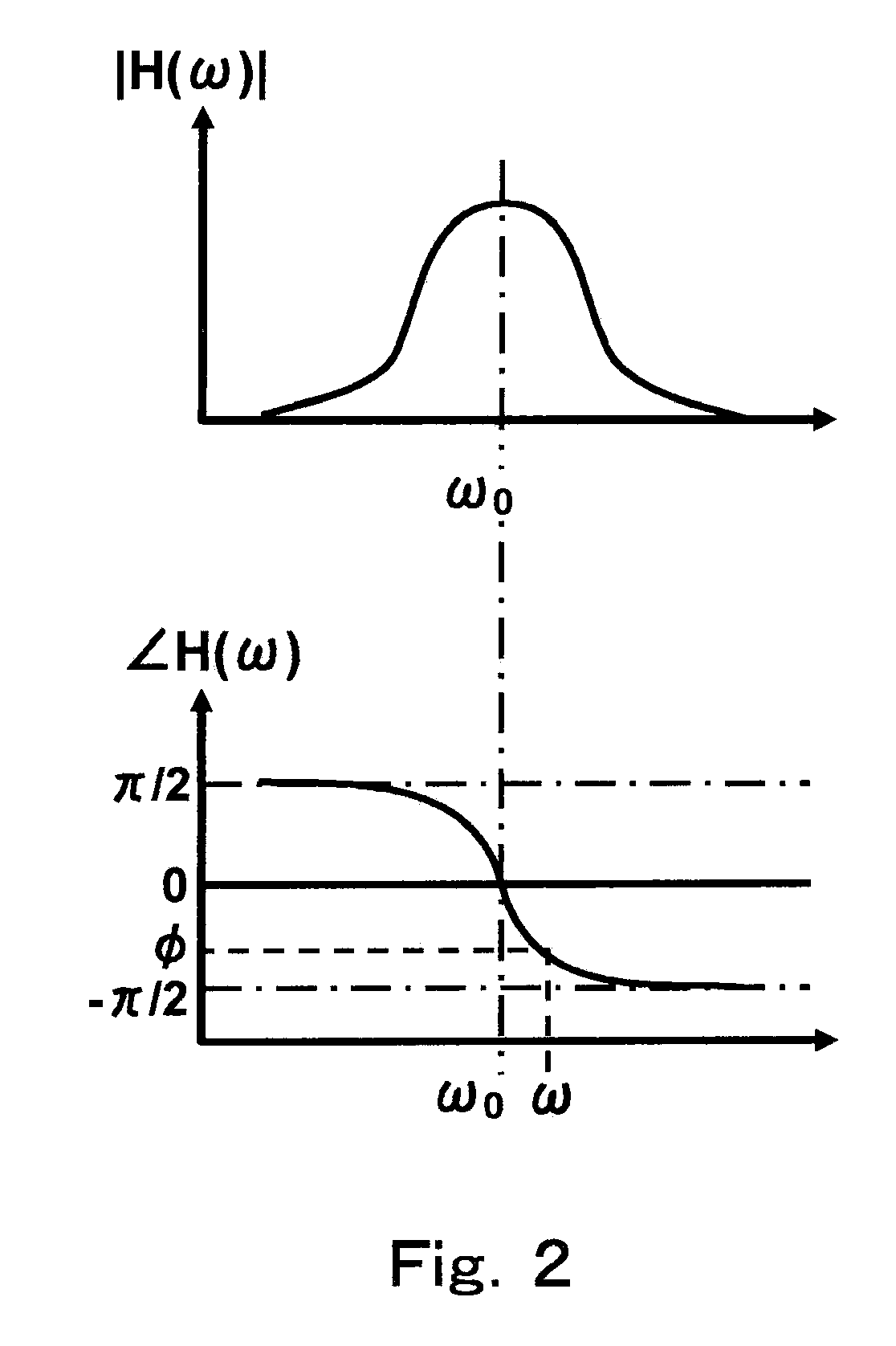
[0089]Further, the phase difference (φI−φQ) between the generated clocks φI and φQ is determined depending on the magnitude relation between ω and ω0, irrespective of the initial state of the circuit components included in the first frequency dividing circuit 102 and the second frequency dividing circuit 103, and therefore, it is possible to realize a clock frequency dividing circuit which is capable of constantly generating stable four-phase clocks with phase guarantee.

[0090]Next, a third embodiment will be described. FIG. 7(a) and FIG. 7(b) show a transconductance amplifier 401b of the clock frequency dividing circuit which is different from the transconductance amplifier 401 in the first embodiment and th...


PUM


Abstract

A first frequency dividing circuit and a second frequency dividing circuit are provided, and these circuits frequency-divide two-phase external clocks injected from an external part, to output four-phase clocks with phase guarantee. Each of the frequency dividing circuits includes a mixer, an adding circuit, and a phase circuit. The first frequency dividing circuit and the second frequency dividing circuit are coupled in loop shape via a first coupling circuit and a second coupling circuit. The first coupling circuit receives a first output signal of the first frequency dividing circuit to output a second external input signal to the second frequency dividing circuit, and the second coupling circuit receives a second output signal of the second frequency dividing circuit to output a first external input signal to the first frequency dividing circuit, and a clock frequency dividing circuit with a high loop gain and a wide lock range can be realized.

Description

CROSS-REFERENCE TO RELATED APPLICATION[0001]This application is a Continuation Application of International Application No. PCT / JP2006 / 303701, filed Feb. 28, 2006, designating the U.S., the entire contents of which are incorporated herein by reference.BACKGROUND[0002]1. Field[0003]The present embodiments relate to a clock frequency dividing circuit generating clocks, and realizing a wide lock range and phase guarantee.[0004]2. Description of the Related Art[0005]In computer and communication fields, an amount of data processed has been recently increasing. In order to cope with the tendency toward an increase in data amount, an operation speed of Large Scale Integrated circuit (LSI) is becoming higher and a data transmission speed between LSIs is becoming higher.[0006]Such speed-up and higher performance of communication and information processing devices are creating a demand for a transmission circuit transmitting / receiving high bit-rate signals and an operation circuit with high ...

Claims


Application Information

Patent Timeline
Patent Type & Authority Applications(United States)
IPC IPC(8): H03B19/06
CPCH03K27/00H03B19/00H03B5/1243H03B5/1228H03B5/1203H03B27/00
Inventor YAMAGUCHI, HISAKATSUKANDA, KOUICHIOGAWA, JUNJITAMURA, HIROTAKA
Owner FUJITSU LTD
Why Eureka
Try Eureka