Magnet Arrays

a technology of magnet arrays and arrays, applied in the field of magnet arrays, can solve the problems of inability to achieve significant leakage beyond the physical boundaries of the workpiece, and achieve the effect of expanding the total magnetic energy available within the devi

Inactive Publication Date: 2009-01-29
MAGSWITCH TECH WORLDWIDE PTY LTD
View PDF33 Cites 59 Cited by
  • Summary
  • Abstract
  • Description
  • Claims
  • Application Information

AI Technical Summary

Benefits of technology

[0044]For Star Array configurations, it is possible to arrange the magnets such that their magnetizing axes all point with their N- or S-poles towards the center, which in effect means that the magnetic energy of the magnets is ‘paralleled’, enlarging the total magnetic energy available within the device, without creating additional flux exchange areas between neighbouring magnets, essentially mimicking a cup magnet with one inner magnetic pole (either S or N) and an outer pole (either N or S).
[0045]Alternatively, in a Star Configu

Problems solved by technology

Over-saturation with significant leakage beyond the p

Method used


Image

  • Magnet Arrays
  • Magnet Arrays
  • Magnet Arrays

Examples


Embodiment Construction

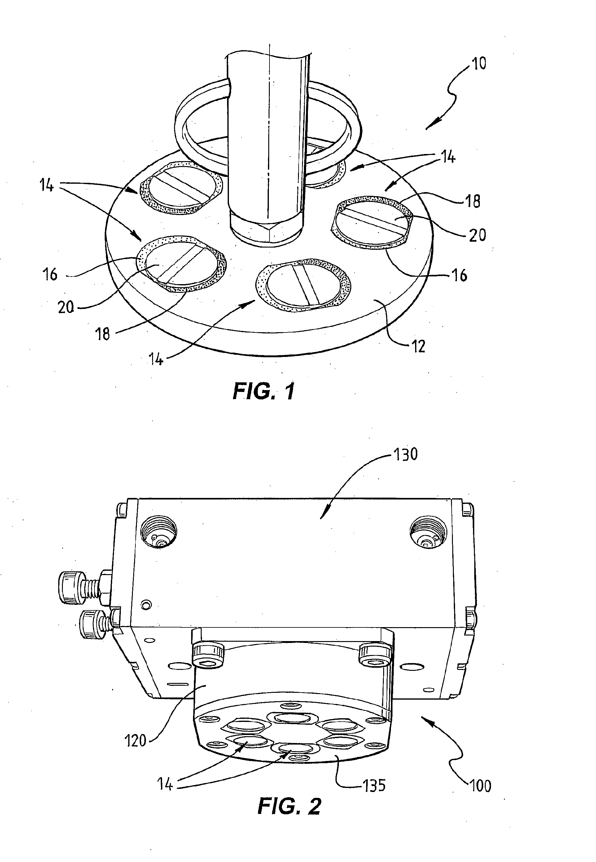
[0072]FIG. 1 illustrates a test-rig-style switchable permanent magnet coupling device 10 incorporating one of the basic concepts underlying the present invention. Embodiments of such magnetic devices may be incorporated into more complex (or simple) apparatus and devices to releasably magnetically couple such device or apparatus to a ferromagnetic body, eg a magnetic lifter as illustrated in FIG. 2 adapted for lifting individual, thin, ferromagnetic sheet metal materials from a stack of such sheets.

[0073]Such device 10 includes a housing or carrier part 12 of substantially non-ferromagnetic material, in this case having a circular plate-like shape, in which are secured against movement five individual, permanent magnet coupling units 14, as will be described below. The units 14 are mounted in apertures that extend through part 12, and may be permanently secured, eg glued, or otherwise secured to allow exchange of individual units. The units 14 are received at part 12 so that at leas...


PUM


Abstract

Method and device for self-regulated flux transfer from a source of magnetic energy into one or more ferromagnetic work pieces, wherein a plurality of magnets, each having at least one N-S pole pair defining a magnetization axis, are disposed in a medium having a first relative permeability, the magnets being arranged in an array in which gaps of predetermined distance are maintained between neighboring magnets in the array and in which the magnetization axes of the magnets are oriented such that immediately neighboring magnets face one another with opposite polarities, such arrangement representing a magnetic tank circuit in which internal flux paths through the medium exist between neighboring magnets and magnetic flux access portals are defined between oppositely polarized pole pieces of such neighboring magnets, and wherein at least one working circuit is created which has a reluctance that is lower than that of the magnetic tank circuit by bringing one or more of the magnetic flux access portals into close vicinity to or contact with a surface of a ferromagnetic body having a second relative permeability that is higher than the first relative permeability, whereby a limit of effective flux transfer from the magnetic tank circuit into the working circuit will be reached when the work piece approaches magnetic saturation and the reluctance of the work circuit substantially equals the reluctance of the tank circuit.

Description

TECHNICAL FIELD[0001]The present invention relates to magnet arrays which can provide a desired magnet field pattern thereby to enable optimised utilization of the magnetic energy contained in the magnets, such as when interacting with a work piece with limited ferromagnetic properties, caused for example by insufficient thickness of the material or its material type.BACKGROUND TO THE INVENTION AND PRIOR ART[0002]The present invention was conceived initially in the context of magnetic lifting devices, but as will become evident from the below description, it has applications beyond devices for hoisting ferromagnetic materials and work piece holders. Development of the invention was effected in the context of permanent magnets but it is believed that the underlying principles are transferable to magnet arrays that employ electromagnets.[0003]Magnetic lifters are versatile material handling devices that use magnetic force to attach one or more ferrous material work pieces, ranging fro...

Claims


Application Information

Patent Timeline
IPC IPC(8): H01F7/04B66C1/04
CPCB25B11/002B66C1/04H01F7/0257H01F7/0273H01F7/02H01F7/0252H01F7/04
Inventor KOCIJAN, FRANZ
Owner MAGSWITCH TECH WORLDWIDE PTY LTD
Why Eureka
Try Eureka