Constructing an Energy Matrix of a Radio Signal

a radio signal and energy matrix technology, applied in the field of radio communication systems, can solve the problems of nakagami fading of individual multi-path components, difficult positioning accuracy, and non-line-of-sight (nlos) propagation,

Inactive Publication Date: 2009-01-29
MITSUBISHI ELECTRIC RES LAB INC
View PDF11 Cites 11 Cited by
  • Summary
  • Abstract
  • Description
  • Claims
  • Application Information

AI Technical Summary

Problems solved by technology

However, in a practical setting, multi-path propagation, multi-user interference (MUI) and non-line-of-sight (NLOS) propagation make accurate positioning challenging.
Because the reflected signal travels a longer distance, a positive bias called a NLOS error is included in a measured time delay.
On the other hand, individual multi-path components are subject to Nakagami fading.
If that suboptimal technique is employed in a narrowband system, then the correlation peak may not give the true TOA because multiple replicas of the transmitted signal partially overlap due to multi-path propagation.
However, those techniques are too complex to perform real time, and requires a large amount of memory.
Even though matched filtering is optimum for leading detection technique, it faces practical problems in implementation.
Matched filtering requires extremely high sampling rates, which is very difficult for UWB systems.
Because the shapes of pulses can be different at various multi-path arrivals, it is very difficult to match the template pulse of the typically analog correlator to the received shape.
Also, it is very difficult to synchronize to each individual multi-path component, which means a loss in the total collected energy.
However, the correlation peak at the output of the matched filter will still not necessarily give the true TOA because the first multi-path component is not always the strongest component.

Method used


Image

  • Constructing an Energy Matrix of a Radio Signal
  • Constructing an Energy Matrix of a Radio Signal
  • Constructing an Energy Matrix of a Radio Signal

Examples


Embodiment Construction

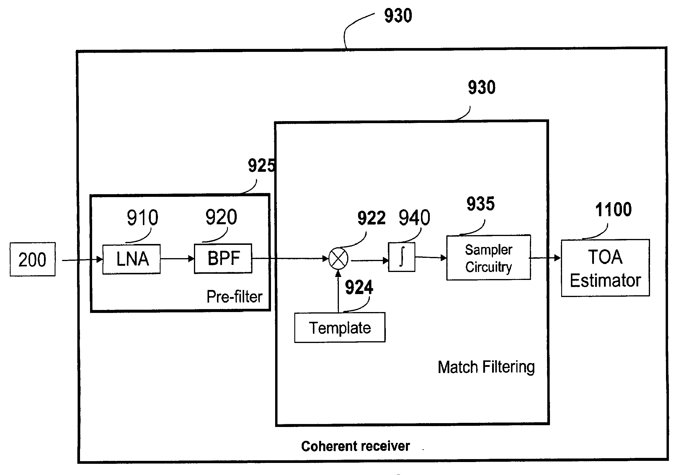
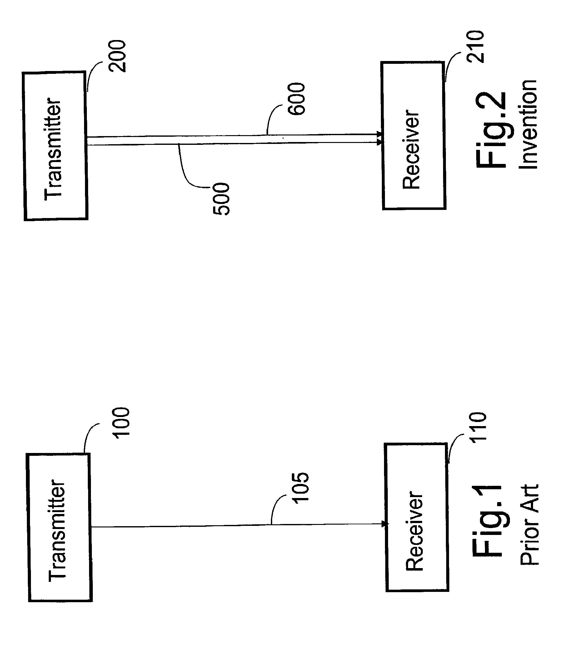
[0046]FIG. 1 shows a communications network with a transmitter 200 and a receiver 210 according to the invention. The transmitter sends a signal 500 or 600 according to the invention to the receiver. In the case of the signal 500 the receiver 210 is coherent, and in the case of signal 600 the receiver is non-coherent.

[0047]Signal Model

[0048]In general, a received signal according to the invention is one of either a narrowband, wideband or ultra-wideband signal (UWB). In the preferred embodiment, the received signal is a time-hopped impulse-radio signal (TH-IR).

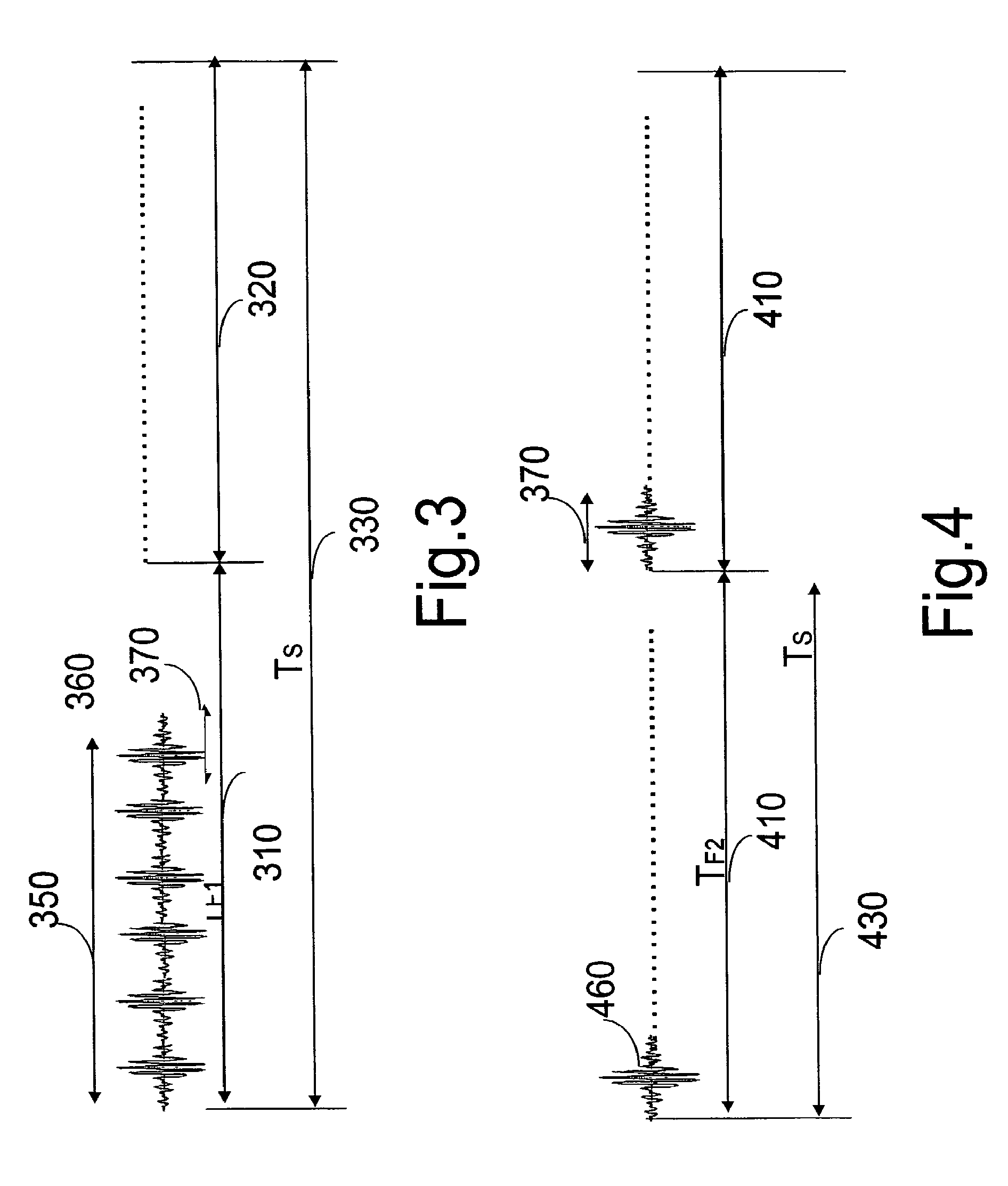
[0049]As shown in FIG. 5 for the signal 500, wireless impulse radio transceivers allocate time in terms of symbol time (TS) 595, frame time (TF) 590, chip times (TC) 505, and pulse event interval 560. A symbol is longer than a frame, and a frame is longer than a block, which is longer than a chip. Each symbol can include multiple frames. Each frame can include multiple chips.

[0050]As shown in FIG. 5, multiple radio pulses 501 ...


PUM


Abstract

A method analyzes a radio signal received via a wireless channel. The radio signal includes multiple frames representing a transmitted symbol. Energy of ach frame is sampled during multiple of non-overlapping time windows. The sampled energies are stored in an energy matrix indexed by the number of frames and the number of time windows in each frame to analyze the radio signal.

Description

RELATED APPLICATION[0001]Our MERL-1682 Filed Friday, Apr. 15, 2005, the contents of which are incorporated herein by reference.FIELD OF THE INVENTION[0002]The present invention relates generally to radio communication systems, and more particularly to constructing an energy matrix to further analyze the radio signal.BACKGROUND OF THE INVENTION[0003]Ranging[0004]To estimate a distance between a transmitter and a receiver in a wireless communications network, the transmitter sends a signal to the receiver at a time instant t1 according to a clock of the transmitter. After receiving the signal, the receiver immediately returns a reply signal to the transmitter. The transmitter measures a time of arrival (TOA) of the reply signal at a time t2. An estimate of the distance between the transmitter and the receiver is the time for the signal to make the round trip divided by two and multiplied by the speed of light c, i.e.,Distance=t1-t22c.This is also known as two-way ‘ranging’.[0005]Ultra...

Claims


Application Information

Patent Timeline
Patent Type & Authority Applications(United States)
IPC IPC(8): H04B1/69H04B17/00H04W84/10H04W88/02
CPCG01S5/0221G01S13/76H04B17/345H04B17/318H04B17/336H04B1/71637
Inventor SAHINOGLU, ZAFERPORIKLI, FATIH M.
Owner MITSUBISHI ELECTRIC RES LAB INC
Why Eureka
Try Eureka