
Interactive visual card-selection process for mitigating light-area banding in a pagewide array

a technology of interactivity visual card and array, which is applied in the direction of electrographic process equipment, printing, instruments, etc., can solve the problems of undercutting the principal advantages, affecting the effect of inkjet dice, etc., and achieves poor perceptual results and cost of adequate scanning equipmen

Inactive Publication Date: 2009-01-29
HEWLETT PACKARD DEV CO LP
View PDF8 Cites 8 Cited by
  • Summary
  • Abstract
  • Description
  • Claims
  • Application Information

AI Technical Summary

Benefits of technology

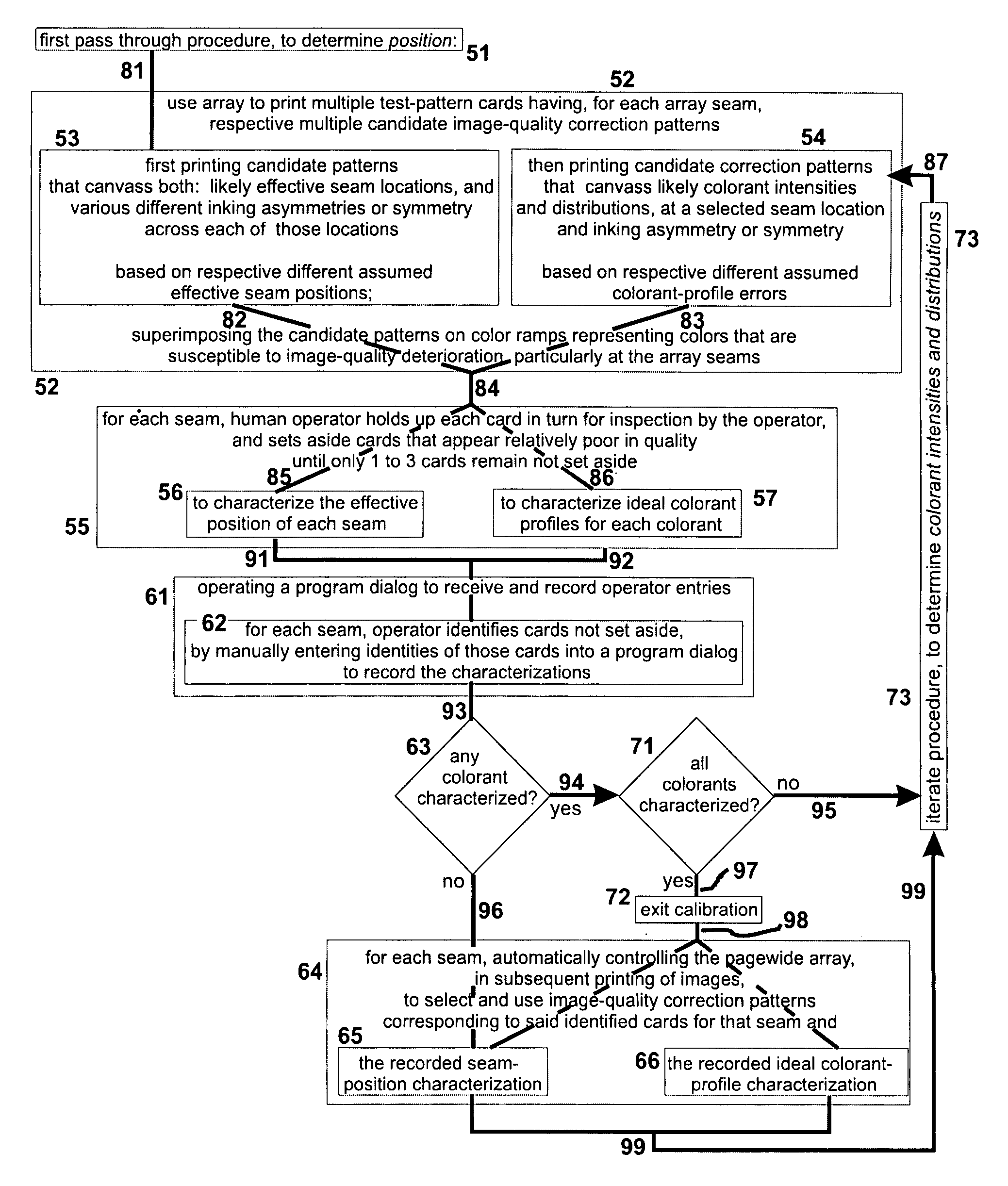
[0026]In preferred embodiments of a first of its facets or aspects, the invention is a method for improving image quality printed by a pagewide printing array. The array is made of several inkjet dice positioned generally end-to-end at array seams. The method steps, described below, are all performed for each seam.
[0030]In particular, by generating and evaluating a separate test-card for each candidate correction pattern, at each seam, the method opens the door to very sophisticated and subtle multidimensional comparisons that draw upon innate complex pattern-recognition capabilities of humans. In particular such comparisons-are very greatly facilitated by the ability to make groupings or subgroupings of the test-cards, and to look at the cards either singly or grouped side-by-side for direct comparison as preferred.
[0031]These capabilities in turn lead directly to more rapid, easier, and more accurate judgments as to settings that will produce best suppression of light-area banding. Other sections of this document provide additional detailed discussion of an operator's options for exploiting the benefits of the using and holding-up steps.
[0043]In particular, this aspect of the invention provides efficient tools that enable an operator to actually perform—in a very short time—accurate comparisons within a very complex interplay of multidimensional factors that all bear on light-area banding. In addition the combination of control system and specialized test-cards establishes a collaboration, between the operator and the machine, that has generally the same advantages described above for the first main aspect of the invention.
[0070]In preferred embodiments of its fourth major independent facet or aspect, the invention is a method for improving image quality printed by a pagewide printing array that is made of several inkjet dice positioned generally end-to-end at array seams. The method includes the step of, at each seam, determining a series of linearization curves for multiple subboundaries, respectively, within the seam.
[0073]In particular, this method causes the overall image to behave as a consistent whole, in terms of both linearization and banding suppression—integrated together. As a result the likelihood is quite small that a conspicuous linearization artifact will arise from correction of banding. The converse is also true, i.e. there is little likelihood that banding will occur as a result of a linearization adjustment. At the same the quality of banding mitigation and the smoothness of blending and merging the banding corrections across the entire width of each boundary is quite good.

Problems solved by technology

In the past, however, such arrays have been somewhat disfavored because—in comparison with scanning printers—as a practical matter they offer relatively little opportunity to mitigate end-effects of individual dice through multipass printing.
Hence, minimizing the number of printing passes in a pagewide system is extremely important; however, adverse image-quality effects that arise at and near the end of each individual inkjet die in a pagewide array are also extremely important.
These adverse effects tend to under-cut the principal advantages and the strong commercial appeal of pagewide printing.
As always, a critical challenge in pagewide printing machines is this tension between design to minimize the number of passes and design to maintain excellent image quality.
First, inkjet dice are not uniform—neither along the length of each die, nor as among the plural dice that make up a single pagewide array. Therefore different imaging properties arise conspicuously in high-volume use of any pagewide array. Due to these nonuniformities, as will be detailed and explained in a later section of this document, typical pagewide arrays are found to print so-called “light-color bands” (in this document used interchangeably with “light-area bands”) along the direction of motion of the printing medium, beneath the arrays.
Second, color printing is expected to perform properly over a very great range of tonal values in the images to be printed for end-customers or other end-users. That is to say, the tonal operating range is not subject to selection by the designer or the printer—or by the printer operator, either. Therefore the light-color banding cannot be avoided by choosing tonal operating range.
Third, from the viewpoint of a system designer, the images themselves likewise must be considered arbitrary, also not subject to selection. In other words, both the designer and the machine operator must take every image that appears in the print queue as they find it. Most particularly, the positional distribution of tonal values within every image is not under control of the designer, the operator or the machine itself in the field. Therefore the light bands also cannot be removed by shifting the image relative to the printing system.
Fourth, as a consequence the positional distribution of tones is likewise not controllable in relation to the individual dice—or, most particularly, in relation to either (1) position alone each die, or (2) specific micro-location of internal portions of the die ends. Once again the machine is expected to somehow do the best possible job of rendering every tone value that arrives for printing, regardless of interactions with the other factors stated above.
Such equipment also must be interfaced with the computing apparatus that controls the printer, and in general this precludes or at least discourages use of third-party scanners whose operating parameters are potentially and in fact usually alien to the computer system.
This is an unfortunate requirement, since such third-party scanners are often available on the open market and often (being necessarily competitive) very economical.
Sixth, and perhaps even more troublesome than other factors discussed above, we have found that even when a high-resolution scanner is used to guide the band-hiding operation of the printer, optimization is less than ideal.
That is, resultant band-hiding as then perceived by human users is not very good—or not as good as desired.
Seventh, although various former procedures are known for controlling incremental printers in response to human input, those former methods fail to provide a satisfactory optimization for light-color banding in pagewide arrays.
Some prior efforts to correct die-generated artifacts may simply overlay corrective colorant patterns onto already-linearized image regions, thus potentially generating a new and different kind of colorant error.
Conclusion—In summary, achievement of uniformly excellent inkjet printing, particularly using pagewide arrays, continues to be impeded by the above-mentioned problems of light-area, light-color bands appearing at or near seams between adjacent printing dice—due to printing nonuniformities at the seams.
Other adverse factors include the cost of adequate scanning equipment, poor perceptual results even when good scanners are used, and too many variables for the simple match-ups used in prior perception-based methods—as well as failure to integrate corrections into the overall linearization scheme of the inkjet printing process.
Another adverse effect may be imprecision of printing-medium advance in the transverse direction, between printing passes.

Method used


Image

  • Interactive visual card-selection process for mitigating light-area banding in a pagewide array
  • Interactive visual card-selection process for mitigating light-area banding in a pagewide array
  • Interactive visual card-selection process for mitigating light-area banding in a pagewide array

Examples


Embodiment Construction

1. Introduction and Overview

[0094]Preferred embodiments of our invention are commonly used to improve image quality of printers in a retail service facility known as a “photo kiosk”. This environment calls for high volume, high throughput, very high reliability, and low unit cost with highly uniform good quality of small printed images.

[0095]Each of these demands militates strongly in favor of pagewide arrays, which involve much less apparatus motion than scanning machines. As explained earlier, however, each pagewide array is susceptible to objectionable light-area banding in the printed images.

[0096]Hence the above objectives of a photo-kiosk printer are advanced by resolution of the banding problem. The reasons for the banding are as follows.

[0097]A pagewide array is made of multiple short inkjet printing elements, “dice”, positioned generally end-to-end but staggered from side to side as will be seen. For various reasons, image portions printed near the seams between adjacent di...


PUM


Abstract

Preferably, test-patterns print on separate, multiple print-medium cards, each including a ramp with colors graded along a certain direction—and, superimposed on the ramp, a candidate add-on colorant. Ramps preferably are printed in so-called “customer colors”, common in snapshots and particularly snapshot regions that include sky. Positions or amounts of the candidate add-on colorant canvass a likely range of values that optimize camouflaging or suppression of a banding artifact (due to seams in the pagewide array) that is extended along the same certain direction. For each seam and each “customer color” used, an operator holds up several cards for comparison, selecting the best one to three. Operators thus can evaluate candidate colorant patterns in context of many different tones of the sky and other customer colors. Preferably banding suppression is integrated with linearization: at each seam a series of linearization tables is smoothly interpolated between measurement-based tables for adjacent inkjet dice.

Description

FIELD OF THE INVENTION[0001]This invention relates generally to incremental printing with a pagewide array, especially an array that is constructed from plural individual printing elements; and more particularly to correction or reduction of color-banding errors made by such an array at seams between adjacent such elements. Most such pagewide arrays of interest for purposes of this document are inkjet devices; thus each printing element in such a device is an inkjet “die” (plural, in this document, “dice”).[0002]Also for purposes of this document, “incremental” printing means printing that is performed a little at a time (e.g. one line at a time), substantially under direct real-time control of a computer (a dedicated computer or a separate general-purpose computer—or combinations of these). Incremental printing thus departs from more-traditional lithographic or letterpress printing, which creates substantially a full-sheet image with each rotation or impression of a press.[0003]Alt...

Claims


Application Information

Patent Timeline
IPC IPC(8): G03G13/00
CPCB41J2/155B41J2202/20B41J2/2132
Inventor GUO, SHILINLI, GUOCHOHAN, ROB PATRICKHUYNH, JULIE
Owner HEWLETT PACKARD DEV CO LP
Learn More