Low transient thermal stress turbine engine components

a technology of low thermal stress and turbine engine, which is applied in the direction of wind motors with perpendicular air flow, machines/engines, waterborne vessels, etc., can solve the problems of thermal stress being more damaging at shutdown, not always possible for a given engine operating condition, and platform actually making the stressing condition wors

Active Publication Date: 2009-01-29
RTX CORP
View PDF16 Cites 48 Cited by
  • Summary
  • Abstract
  • Description
  • Claims
  • Application Information

AI Technical Summary

Problems solved by technology

The two platforms actually make the stressing condition worse by forcing the leading edge deformation onto the trailing edge.
Also, since the shutdown conditions produce high tensile stress, the thermal stress is more damaging at shutdown than at start-up conditions.
That is, however, not always possible for a given engine operating condition and, in particular, when the turbine engine component is composed of low strength materials.

Method used


Image

  • Low transient thermal stress turbine engine components
  • Low transient thermal stress turbine engine components
  • Low transient thermal stress turbine engine components

Examples


Embodiment Construction

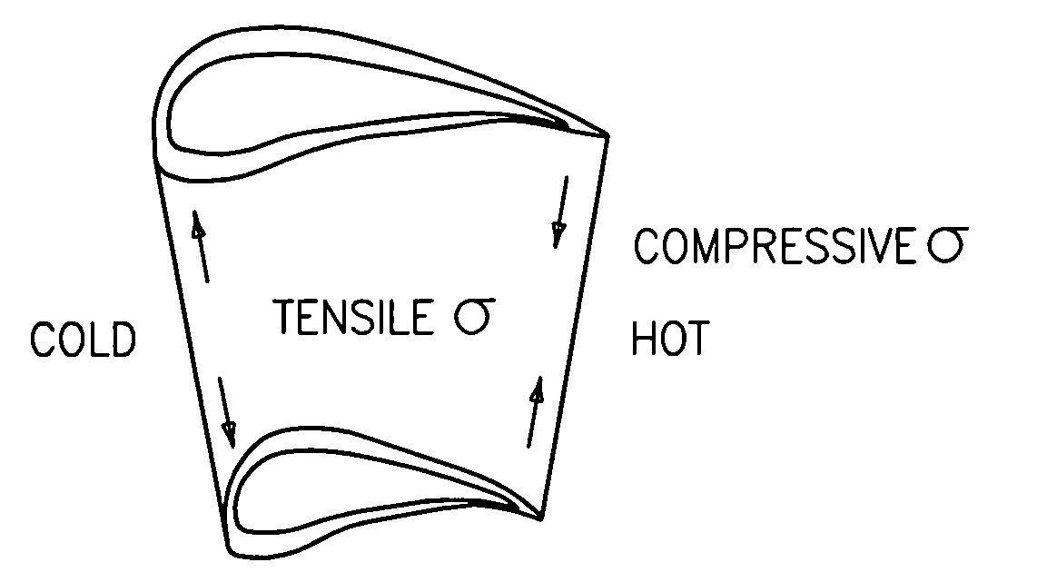
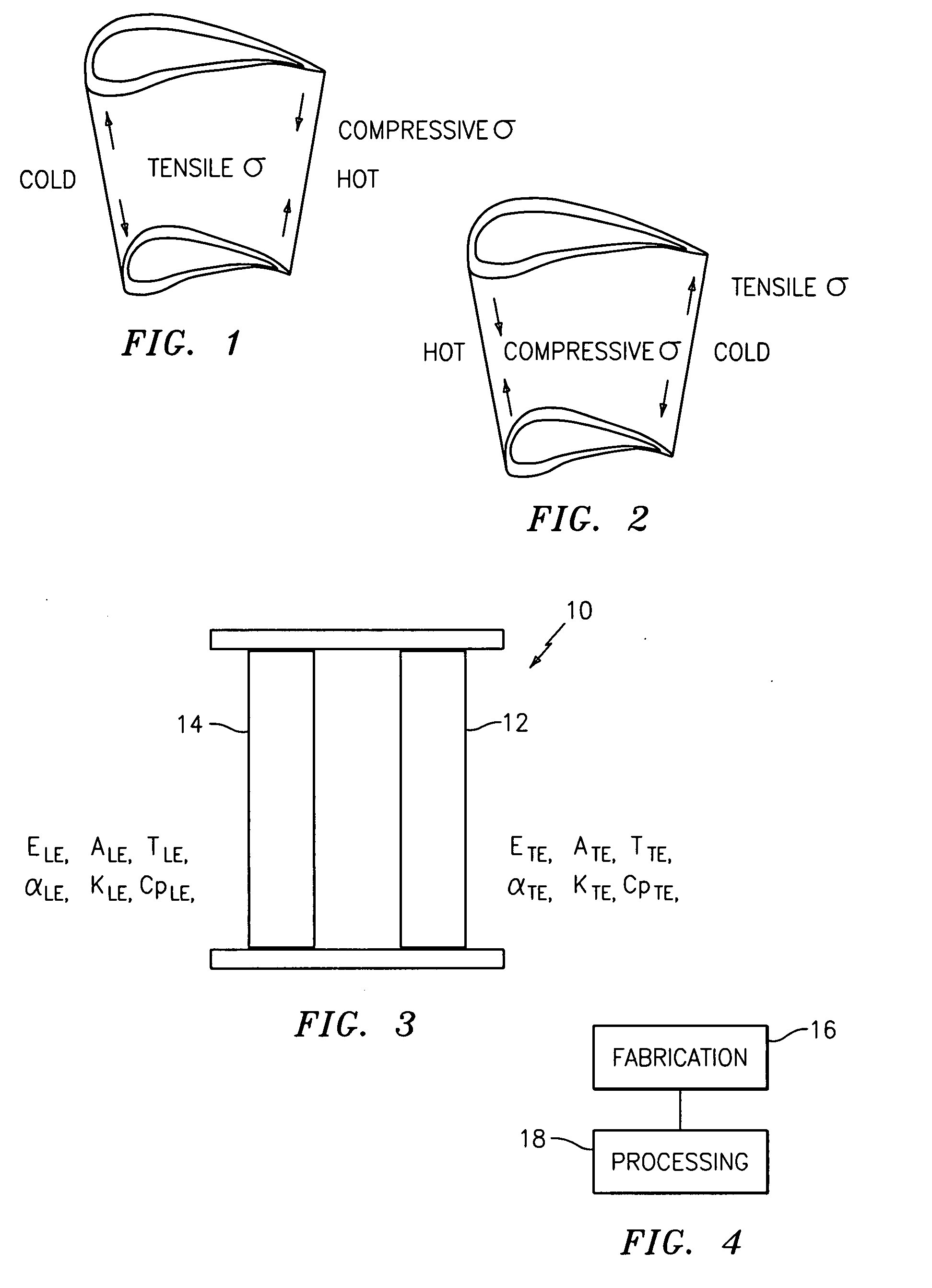
[0019]Referring now to FIG. 3, the thermal stresses experienced by a turbine engine component, e.g., a turbine vane 10, may be demonstrated using a thermal stress model represented by a two bar system. The thermal stress in a trailing edge 12 of the vane 10 may be represented by the two bar system by the following equation:

σTE=TLEαLE-TTEαTEELE / ETE+ATE / ALEELE(1)

where the subscript LE denotes the leading edge, the subscript TE denotes the trailing edge, T is the temperature, α is the thermal expansion coefficient, A is the cross-sectional area, and E is the Young's modulus. Formula (I) assumes a zero stress state at room temperature. If this is not true and a stress free state exists at another temperature T0, then Formula (I) should be modified as follows:

σTE=(TLE-T0)αLE-(TTE-T0)αTEELE / ETE+ATE / ALEELE(2)

[0020]In accordance with both Formulas (1) and (2), the thermal stress at the trailing edge 12 may be primarily controlled by the thermal expansion mismatch (TLEαLE-TTEαTE) and the lea...


PUM

PropertyMeasurementUnit
thermal stress modelaaaaaaaaaa
thermal stressaaaaaaaaaa
morphologiesaaaaaaaaaa

Abstract

A turbine vane includes a platform; and at least one airfoil mounted to the platform and having a trailing edge and a leading edge, wherein the vane is composed of a functionally graded material having a first material and a second material, wherein the trailing edge includes a greater amount of the first material than the second material, and the leading edge includes a greater amount of the second material than the first material.

Description

GOVERNMENT RIGHTS[0001]The United States Government may have certain rights in the invention pursuant to contract number DE-FC02-00CH11060 awarded by the Department of Energy.FIELD OF THE INVENTION[0002]The invention relates to turbine engine components and, more particularly, relates to low thermal stress turbine engine components.BACKGROUND OF THE INVENTION[0003]Referring to FIGS. 1 and 2, turbine vanes in a gas turbine engine are exposed to high temperature combustion gas which imparts an intensive heat load onto the vanes. Since aerodynamic design of turbine vanes stipulates a thin trailing edge, the heat load leads to a chordwise temperature gradient in the vane. The thinner wall at the trailing edge means a lower thermal mass and thus translates into experiencing a higher temperature than the thicker leading edge under steady state conditions. During transient conditions such as engine start-up (See FIG. 1) or shutdown (See FIG. 2), the thin trailing edge would heat-up or cool...

Claims


Application Information

Patent Timeline
Patent Type & Authority Applications(United States)
IPC IPC(8): F01D5/28B21D53/00F04D29/44
CPCF01D5/147F01D5/28Y10T29/4932F05D2300/50212F05D2230/30B33Y80/00
Inventor SHI, JUNSCHMIDT, WAYDE R.
Owner RTX CORP
Why Eureka
Try Eureka