
Magnetic device and manufacturing method thereof

a technology of magnetic devices and manufacturing methods, applied in the direction of inorganic material magnetism, vehicle sealing arrangements, inductances, etc., can solve the problems of limited usable material of coils b>23/b>, restricted miniaturization of conventional magnetic devices, and limited use of copper wires and magnetic cores. , to achieve the effect of high inductance, good magnetic properties and thin thickness

Inactive Publication Date: 2009-01-29
DELTA ELECTRONICS INC
View PDF4 Cites 43 Cited by
  • Summary
  • Abstract
  • Description
  • Claims
  • Application Information

AI Technical Summary

Benefits of technology

The invention is a magnetic device and a manufacturing method that can be thinner and have higher inductance. The method involves forming a magnetic substrate with a recess and then placing a coil in the recess. This results in a thinner device and higher inductance. The magnetic substrate can be made from ferrite, which allows for good magnetic properties. The material of the coil is not limited because of the high temperature process.

Problems solved by technology

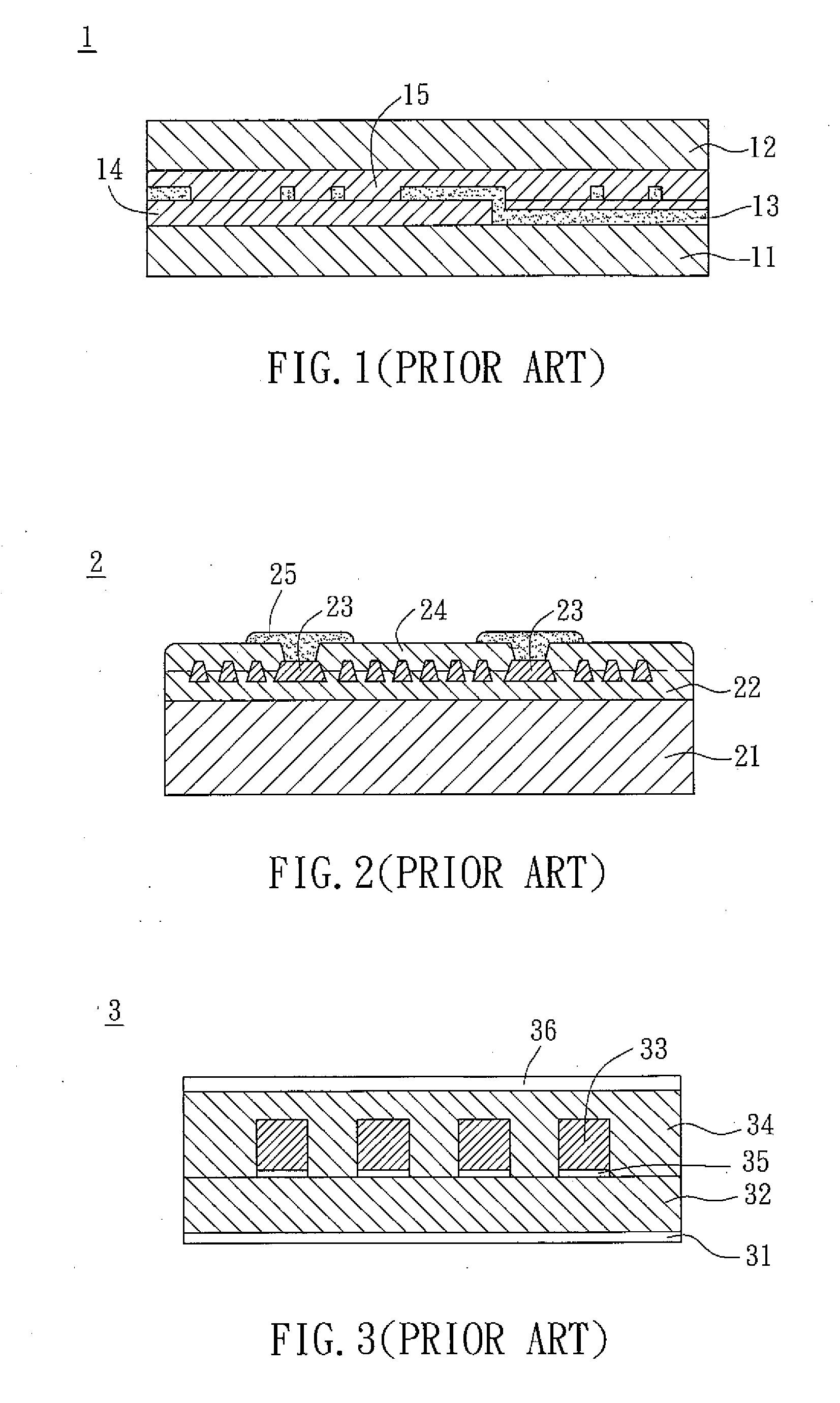
However, the miniaturization of the conventional magnetic devices is restricted by the conventional manufacturing apparatuses, the width of the copper wires and the size of the magnetic cores.
However, since the sintering temperature is up to 1000° C. to 1200° C., the usable material of the coil 23 is limited.
However, the magnetic properties of the ferrites 32 and 34 made by a ferrite plating method are poorer than that of the ferrites made by sintering.

Method used


Image

  • Magnetic device and manufacturing method thereof
  • Magnetic device and manufacturing method thereof
  • Magnetic device and manufacturing method thereof

Examples


Embodiment Construction

[0023]The present invention will be apparent from the following detailed description, which proceeds with reference to the accompanying drawings, wherein the same references relate to the same elements.

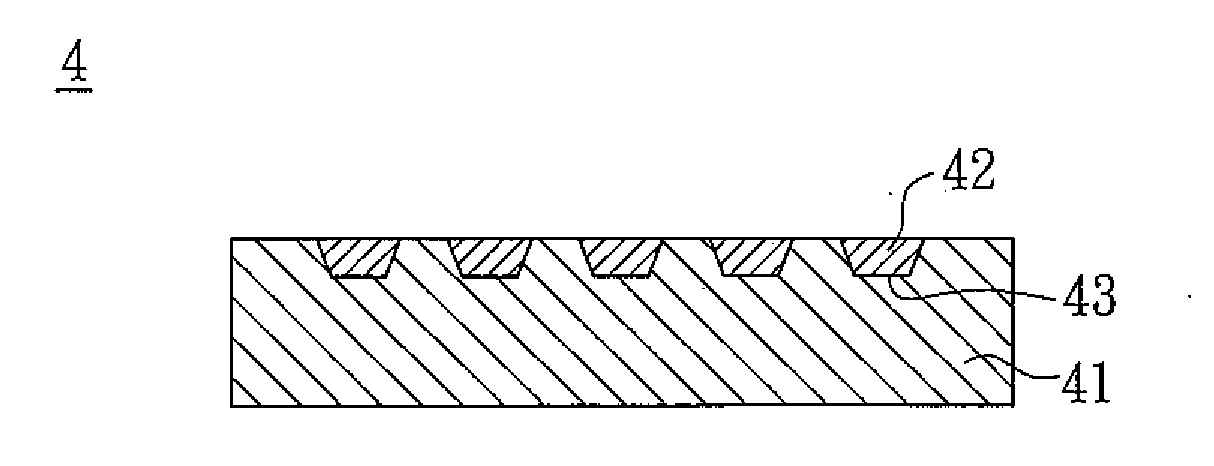
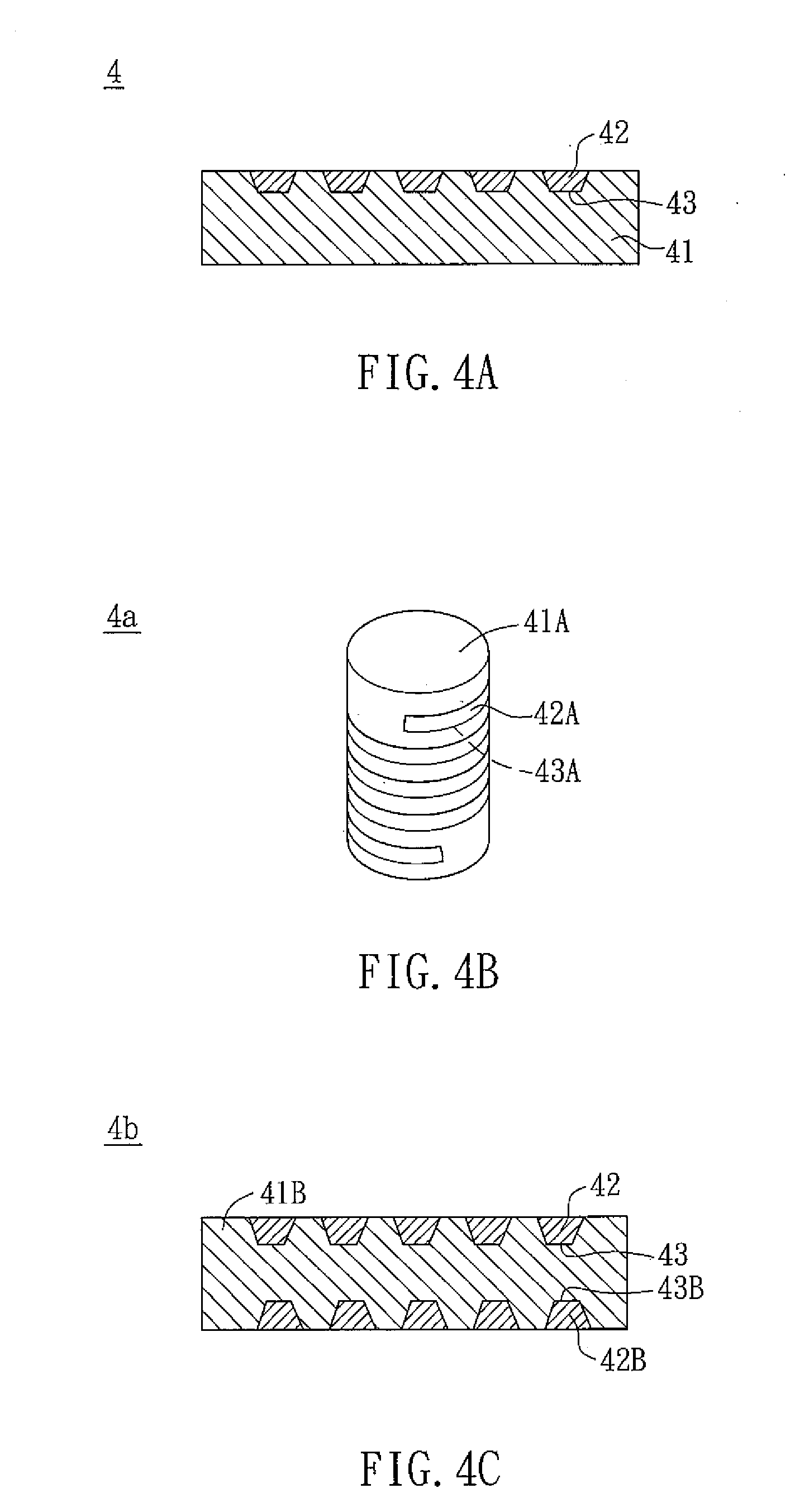
[0024]As shown in FIG. 4A, a magnetic device 4 according to an embodiment of the invention includes a magnetic substrate 41 and at least one coil 42. The magnetic substrate 41 can be formed by sintering or curing. The magnetic substrate 41 has at least one recess 43 disposed on one side of the magnetic substrate 41 for accommodating the coil 42. If the magnetic substrate 41 is formed by sintering, the material of the magnetic substrate 41 can be ferrite mixed with a binder. The ferrite can be, for example, NiZn ferrite or MnZn ferrite. If the magnetic substrate 41 is formed by curing, the material of the magnetic substrate 41 can be a metal soft magnetic powder mixed with a polymer material as the isolation among magnetic particles. In addition, the material of the coil 42 can be allo...


PUM

PropertyMeasurementUnit
temperatureaaaaaaaaaa
magneticaaaaaaaaaa
non-magneticaaaaaaaaaa

Abstract

A manufacturing method of a magnetic device includes the steps of forming a magnetic substrate having a plurality of recesses, and forming at least one coil in the recess. In addition, a magnetic device is also disclosed. The magnetic device includes a magnetic substrate and at least one coil. The magnetic substrate has a plurality of recesses and the coil is disposed in the recess.

Description

CROSS REFERENCE TO RELATED APPLICATIONS[0001]This Non-provisional application claims priority under 35 U.S.C. §119(a) on Patent Application No(s). 096127440 filed in Taiwan, Republic of China on Jul. 27, 2007, the entire contents of which are hereby incorporated by reference.BACKGROUND OF THE INVENTION[0002]1. Field of Invention[0003]The invention relates to a magnetic device and a manufacturing method thereof.[0004]2. Related Art[0005]Magnetic devices have been widely applied to inductors or noise filters of electronic products. The conventional magnetic devices are made by winding enameled copper wires around magnetic cores. However, the miniaturization of the conventional magnetic devices is restricted by the conventional manufacturing apparatuses, the width of the copper wires and the size of the magnetic cores. Compared with the conventional manufacturing method of winding, the micro-fabrication technology can bring smaller inductors and filters, such as the common-mode noise f...

Claims


Application Information

Patent Timeline
Patent Type & Authority Applications(United States)
IPC IPC(8): H01F41/02H01F5/00
CPCH01F1/26H01F1/37H01F5/003Y10T428/12201H01F17/04H01F41/046H01F2017/0066H01F17/0006
Inventor LEE, CHENG-CHANGLIN, MING-HSIENCHANG, YU-RUYUAN, ZONG-TINGCHANG, HENG-CHUNGCHEN, HUANG-KUNSHING, TAI-KANG
Owner DELTA ELECTRONICS INC
Learn More