Multi-band radio communication method and base station

a radio communication and multi-band technology, applied in the field of multi-band radio communication methods, can solve the problems of high-speed transmission, many connection errors in the system, and severe allocation of low frequency, and achieve the effect of wide service area

Inactive Publication Date: 2009-01-29
MITSUBISHI ELECTRIC CORP
View PDF11 Cites 85 Cited by
  • Summary
  • Abstract
  • Description
  • Claims
  • Application Information

AI Technical Summary

Benefits of technology

[0012]According to the present invention, a high-frequency band capable of accommodating a large number of users can be preferentially allocated to users, and a high-speed and wide service area can be realized in the entire communication system.

Problems solved by technology

Consumers are not interested in purchasing a system having many connection errors, even the system's connection is performed at a high speed.
However, high-speed transmission is contradictory to a service area in many aspects.
Because high-speed transmission requires a broad band, allocation of a low frequency is severe, and use of a high-frequency band having room is unavoidable.
However, because of a physical constraint, when a high frequency is used, sufficient communication cannot be performed on NLOS propagation channels.
Specifically, in the frequency of 3 gigahertz or above, there is a risk that a wave does not sufficiently reach indoors from outdoors, and consumers do not easily accept a reduction of service coverage.
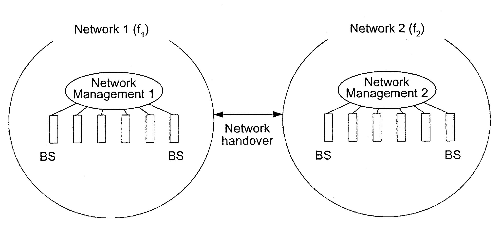
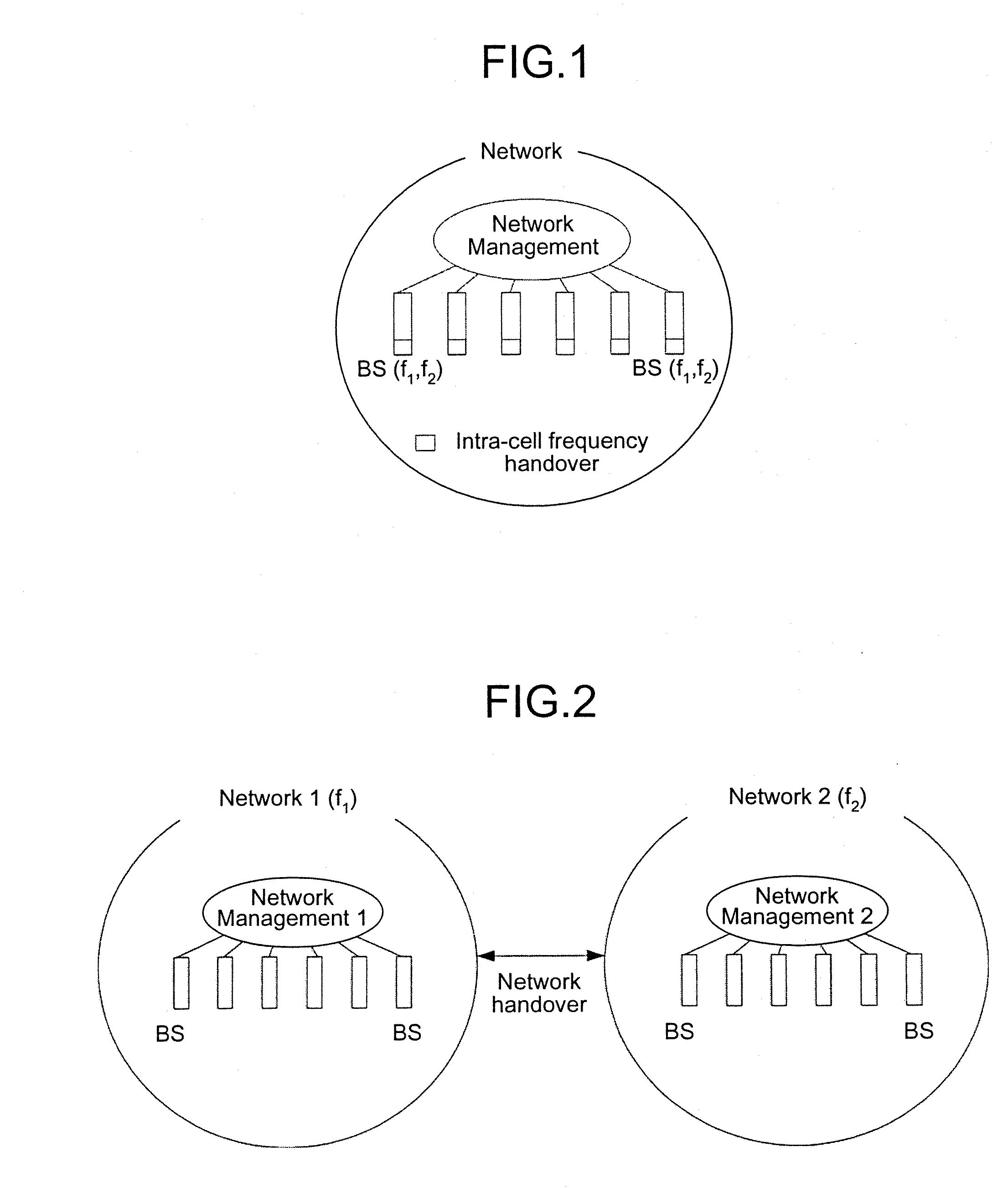
However, there are complex problems such as charges from a provider, delay and control load of network handovers, and a problem that a user needs to purchase various kinds of system.
However, these technologies do not suggest management of traffics in a plurality of bands.

Method used


Image

  • Multi-band radio communication method and base station
  • Multi-band radio communication method and base station
  • Multi-band radio communication method and base station

Examples


first embodiment

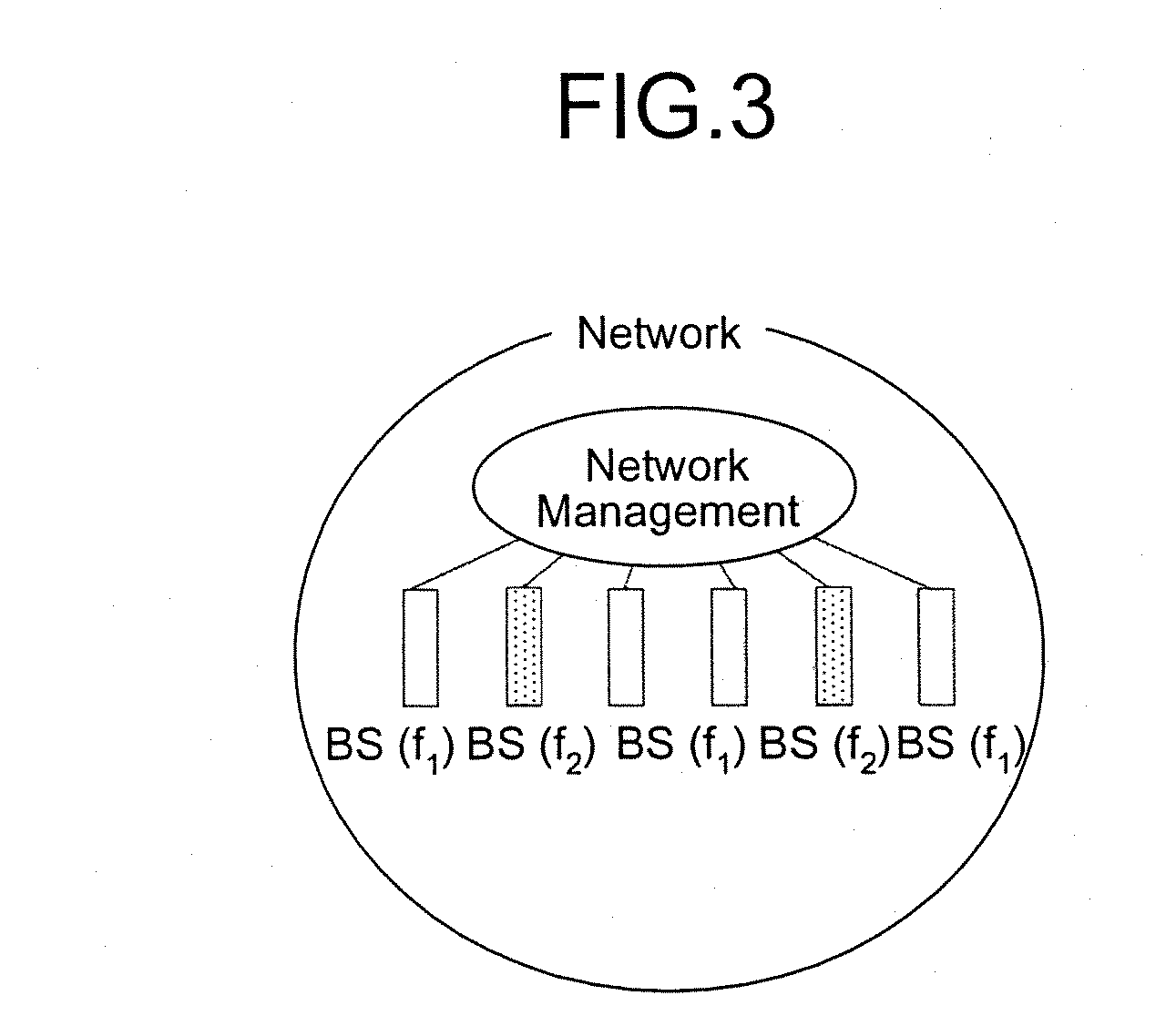
[0063]An outline of a multi-band radio communication method according to the present invention is explained first. The present invention explains a new communication system capable of performing high-speed transmission while maintaining high service coverage in a single system, that is, a multi-band radio communication method. The method uses a plurality of wide-separated frequency bands having a difference of propagation and diffraction characteristics, unlike conventional communication using a single frequency band. Usually, a mobile station performs communication using a high frequency, and uses a low frequency only when a propagation state of a high frequency is poor. According to the conventional radio communication, a low frequency is also used on a Line-of-Sight (LOS) path. According to this first embodiment, valuable low-frequency resource is effectively used by limiting the use of a low frequency to an absolutely necessary case. While the multi-band radio communication meth...

second embodiment

[0077]The operation according to a second embodiment is explained next. Constituent elements similar to those of the first embodiment described above are denoted by like reference numerals and explanations thereof are omitted. Only processes different from those of the first embodiment described above are explained below.

[0078]FIG. 7 is an example of a method of allocating bands by the channel controller 9, different from the first embodiment described above. In FIG. 7, Ba denotes a radio resource amount required by a mobile station, A1, A2, A3 indicate the amounts of radio resources of the system corresponding frequency bands, and B1, B2, B3 indicate the amounts of radio resources currently used in respective frequencies. The radio resource amounts are parameters representing capacities of the system, and are given as a communication transmission speed, a band used, and a corresponding number of reference mobile stations.

[0079]According to the present embodiment, a mobile station r...

third embodiment

[0082]The operation according to a third embodiment is explained next. Constituent elements similar to those of the first embodiment described above are denoted by like reference numerals and explanations thereof are omitted. Only processes different from those of the first or second embodiment described above are explained below.

[0083]FIG. 23 and FIG. 24 are examples of a method of allocating bands by the channel controller 9, different from the first embodiment described above. In the system similar to that of the first embodiment, a mobile station usually performs communication using a frequency having a broad cover area. A mobile station can easily move due to usage of a low frequency. On the other hand, when the low-frequency band becomes full and when the band cannot accommodate an additional mobile station any more, the mobile stations are sequentially changed to high-frequency mobile stations. The switching is determined based on a position of a mobile station, a state of th...


PUM


Abstract

In a radio communication system that simultaneously provides communication service using a plurality of discontinuous frequency bands, a multi-band radio communication method according to the present invention is a method in which a base station constituting the system allocates a band to a mobile station that requests a communication starting. For example, a specific receiving unit within the base station extracts control information concerning a channel state in each of the frequency bands, and recognizes a frequency band in which the mobile station can receive information, from a result of the extraction. A channel controller 9 determines, starting from a high frequency band, whether a new traffic responding to the communication starting request can be allocated in each frequency band.

Description

TECHNICAL FIELD[0001]The present invention relates to a multi-band radio communication method for simultaneously providing communication services through a plurality of frequency bands, and more particularly, to a multi-band radio communication method for preferentially allocating a high-frequency band to a mobile station.BACKGROUND ART[0002]At present, researches of efficient high-speed radio transmission are actively performed, in the background of high expectation for future-generation high-speed radio transmission. In considering a communication system as business, consumers are conscious about a service area of the system as well as its transmission speed. Consumers are not interested in purchasing a system having many connection errors, even the system's connection is performed at a high speed. This is recognized from a relationship between population coverage and a subscriber increase in businesses in the past. In this sense, maintaining high service coverage is an important ...

Claims


Application Information

Patent Timeline
Patent Type & Authority Applications(United States)
IPC IPC(8): H04W72/00H04M1/00H04J1/00H04W52/02H04W72/04
CPCH04L5/023H04W52/0216H04W72/08Y02D30/70H04W72/54
Inventor OCHIAI, MARITAIRA, AKINORIHARA, YOSHITAKA
Owner MITSUBISHI ELECTRIC CORP
Why Eureka
Try Eureka