FIG. 23 is an illustration of the basic principle of the HDR system. It is generally known that the signal transmitted toward terminals from a base
station (hereinafter, called down-link signal) is attenuated in its power in inverse proportion to the distance to the power 3.5 in, for example, large cities. The power of the down-link signal is reduced to a lower level than a signal transmitted from a nearby base
station or than an interference signal due to thermal
noise or the like as it is transmitted a long way from the base station, and thus the terminal is difficult to normally receive the desired signal. The ratio of this received signal power to the interference power is called the carrier-to-
interference ratio, or C / I. When this C / I is high enough at near the base station, a
radio signal of, for example, 8-level, or multi-level modulation system is used, and the error correction redundancy is reduced because the
radio wave is of high quality, resulting in use of the same bandwidth. Even in this case, the signal can be transmitted at a high
bit rate. On the other hand, in an area distant from the base station, the C / I is low, and thus it is necessary to use a reduced-level modulation such as binary system in which error is difficult to occur, and to enhance the error correction capability by increasing the signal redundancy. As a result, the
bit rate at which the desired signal can be transmitted is reduced. In the HDR system, the C / I is measured at the terminal before communication begins, and the
maximum bit rate that can be used in that area is reported to the base station, thereby eventually achieving the best effort type
wireless transmission system.
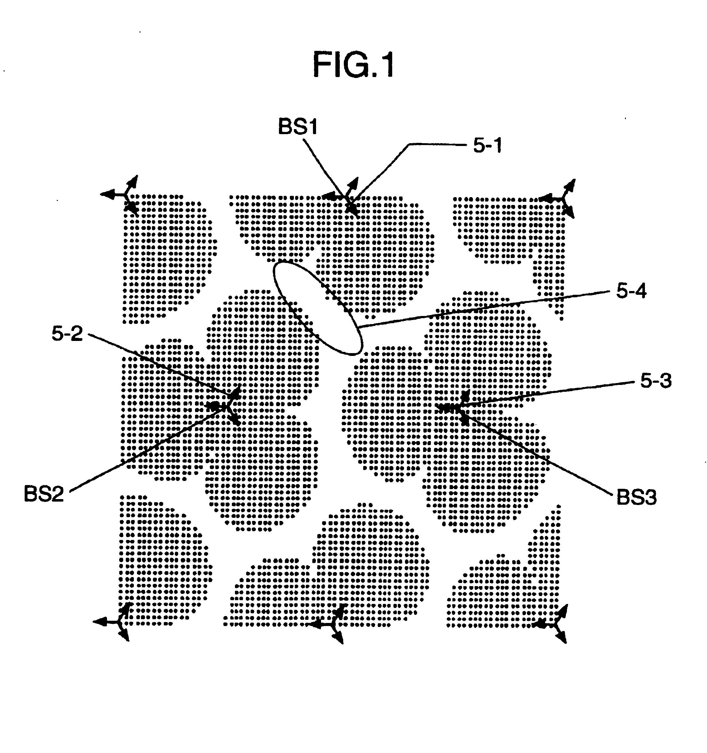
In view of the above points, it is an object of the invention to provide a wireless communication method in the base station system, by which sufficiently high-bit rate communications particularly in the boundary regions between the cells or sectors in the HDR system can be prevented from being made difficult by the interference between the radio
waves radiated from the base stations.
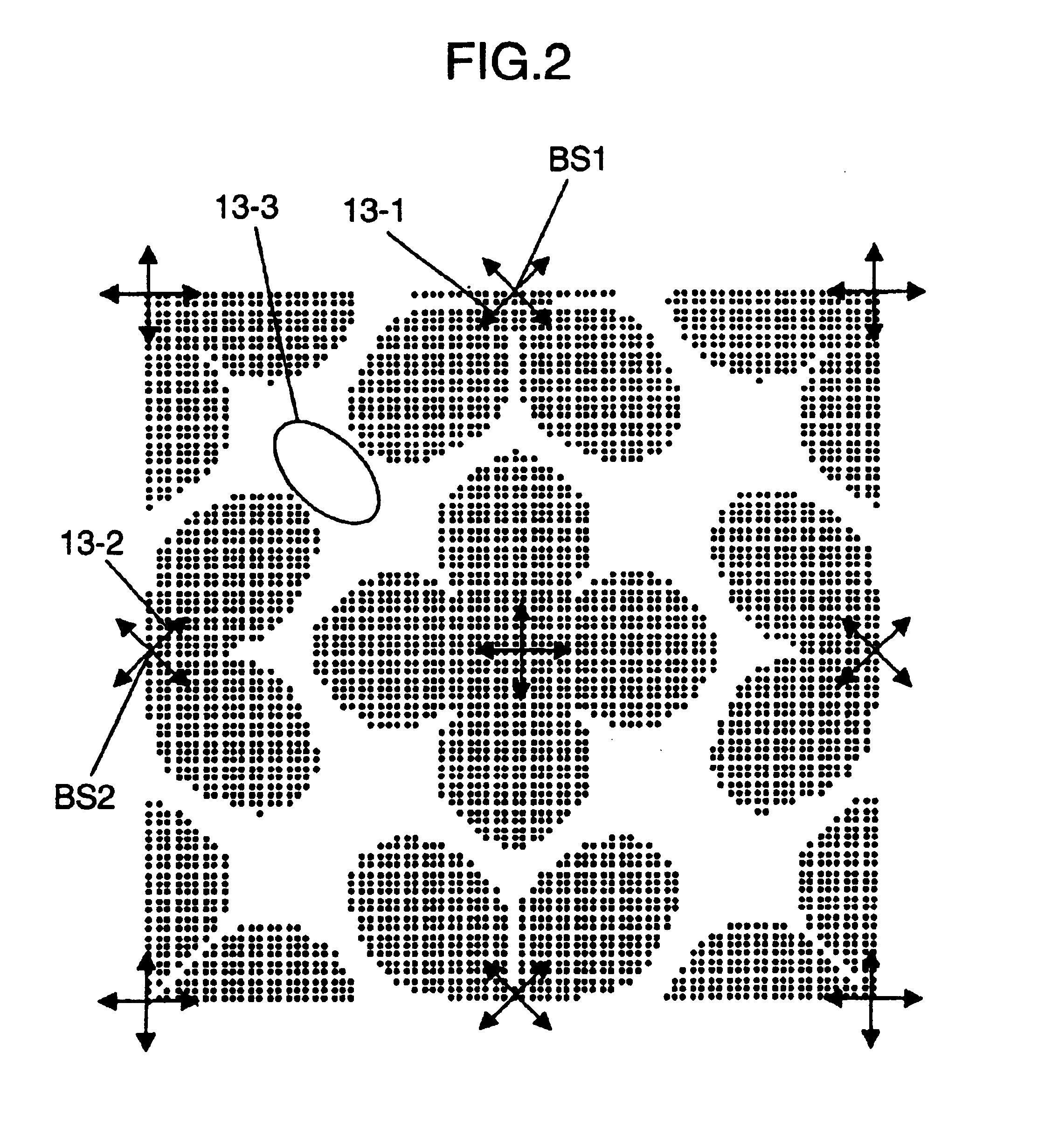
It is another object of the invention to provide a wireless communication method that can reduce the areas toward which the sector beams are not directed, and thereby offer a wider service area.
It is still another object of the invention to provide a wireless communication method that can reduce, as much as possible, the degree of the deep entering of the service disabled region into the service area as a result of the interference between a plurality of sector beams.
It is still another object of the invention to provide a wireless communication method that enables the terminal, or user, wherever it is, to always receive a satisfactory
radio wave signal that is almost not disturbed by other signals by, for example, controlling the simultaneous radiations of radio
waves from the base stations on the HDR down-link to be made in the directions in which they are most difficult to interfere with each other. Accordingly, it is still another object of the invention to make full use of one of the features of the HDR, or the fact that high bit rate communications can be made when the radio interference is small.
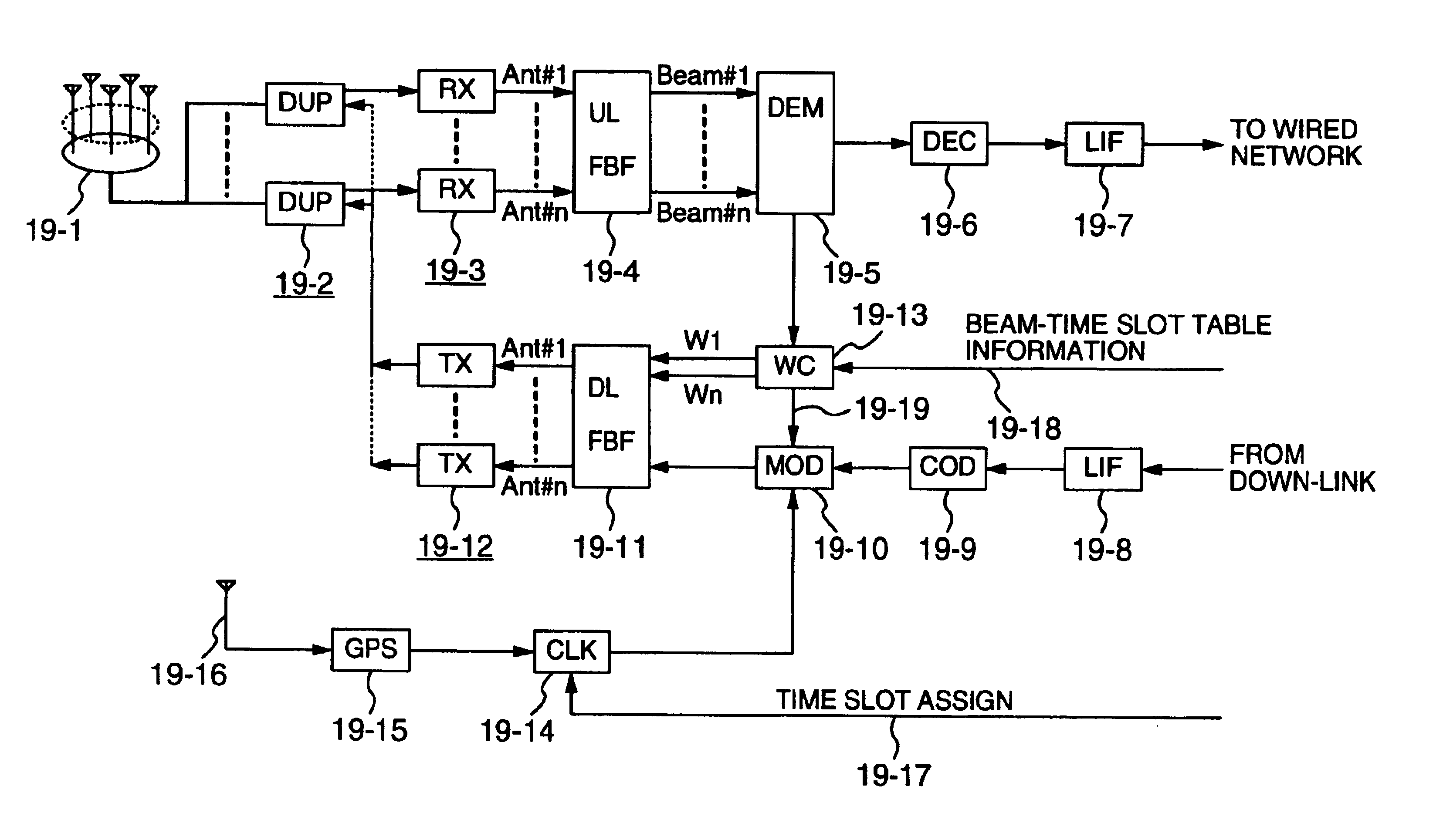
The present invention, in order to prevent the radio
waves from the respective base stations from interfering with each other, is to control the radio waves interfering with each other not to be radiated at a time, but radiated at different times, thereby avoiding the interference. At this time, the operations of the respective base stations are managed to be precisely synchronized with each other and so that the directions in which the base stations radiate radio waves can be timely switched to avoid the interference, by making use of a system that can supply the absolute time with high precision and over a
wide area, such as the GPS system.

