Agricultural working machine

Active Publication Date: 2009-01-29
CLAAS SELBSTFAHRENDE ERNTEMASCHINEN GMBH
View PDF26 Cites 19 Cited by
  • Summary
  • Abstract
  • Description
  • Claims
  • Application Information

AI Technical Summary

Benefits of technology

[0006]The object of the present invention, therefore, is to avoid the disadvantages of the cited related art and to refine an agricultural working machine of the type described initially such that dangerous situati

Problems solved by technology

The disadvantage of this embodiment is that it is not possible to adjust the tire pressure to changing circumstances immediately.
When a forage harvester is driven at permissible ground speeds of u

Method used


Image

  • Agricultural working machine
  • Agricultural working machine
  • Agricultural working machine

Examples


Embodiment Construction

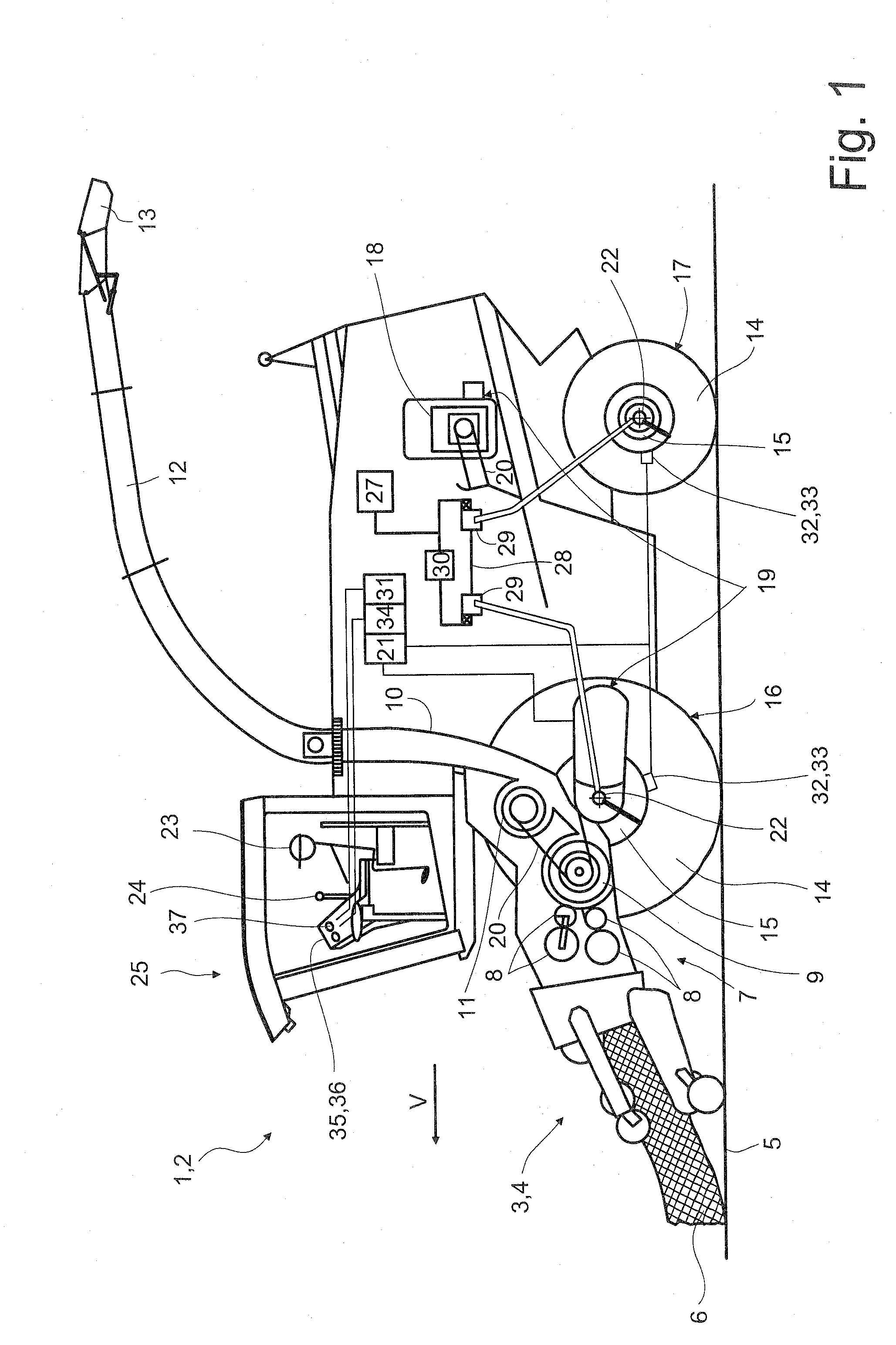
[0018]FIG. 1 shows an agricultural working machine 2 designed as a forage harvester 1, which includes a front attachment 4 designed as a pick-up 3, which picks up crop material 6, e.g., grass, lying on ground 5. In pick-up 3, picked-up crop material 6 is compressed to the width of intake conveyor mechanism 7 and is passed on to intake conveyor mechanism 7. Crop material 6 is then compressed between intake rollers 8 located in intake conveyor mechanism 7 and is conveyed further to downstream chopper drum 9. Rotating chopper drum 9 chops crop material 6 into a specifiable post-accelerator 11 engages in the crop material flow and accelerates it along upper discharge chute 12 to ensure it is transferred reliably to a not-shown hauling container. A discharge flap 13 for determining the outflow direction of crop material 6 is located at the end of discharge chute 12. Forage harvester 1 also includes front wheels 16, which are composed of a tire 14 and a wheel rim 15, and rear wheels 17. F...


PUM


Abstract

The present invention relates to an agricultural working machine (2), in particular a forage harvester (1) with a device for adjusting the ground speed v, with which the maximum ground speed v of the agricultural working machine (2) is determined as a function of the tire pressure of at least one tire (14).

Description

CROSS-REFERENCE TO A RELATED APPLICATION[0001]The invention described and claimed hereinbelow is also described in German Patent Application DE 10 2007 035 647.3 filed on Jul. 27, 2007. This German Patent Application, subject matter of which is incorporated herein by reference, provides the basis for a claim of priority of invention under 35 U.S.C. 119(a)-(d).BACKGROUND OF THE INVENTION[0002]The present invention relates to an agricultural working machine with a device for adjusting the ground speed.[0003]With agricultural working machines such as forage harvesters, there is a need to adjust the air pressure in the tires depending on the ground being driven over, in particular to reduce the stress on the ground. Lowering the tire pressure increases the ground contact area, which results in less damage being done to the ground being driven over. The tire pressure is increased for street driving, however, since a higher pressure is required at high speeds to prevent tire damage.[0004]...

Claims


Application Information

Patent Timeline
IPC IPC(8): G06F19/00A01F29/09
CPCA01D41/127A01D43/085B60Y2200/222B60W2530/20B60Y2200/22B60C23/00
Inventor POLLKLAS, MANFREDIMMER, DANIEL
Owner CLAAS SELBSTFAHRENDE ERNTEMASCHINEN GMBH
Why Eureka
Try Eureka