Expansion valve control system and method for air conditioning apparatus

a control system and air conditioning technology, applied in lighting and heating equipment, process and machine control, instruments, etc., can solve the problems of inability to provide suitable control over refrigerant fluid flow, inability to provide economic practicability, and inability to reliably operate, so as to reduce the chance of damage to the system compressor

Active Publication Date: 2009-02-05
TRANE INT INC
View PDF15 Cites 65 Cited by
  • Summary
  • Abstract
  • Description
  • Claims
  • Application Information

AI Technical Summary

Benefits of technology

[0003]The present invention provides an improved air conditioning apparatus or system including an electronic control system for controlling the refrigerant working fluid expansion valve to control fluid superheat prior to introducing the fluid to the system compressor. The present invention also provides an improved method of controlling working fluid flow in a vapor compression type air conditioning system to minimize the chance of damage to the system compressor during certain phases of operation.
[0006]A method in accordance with the invention provides, during steady state operation, for an estimate of future changes in evaporator temperature based on historical changes in expansion valve position, and adjustments to valve position are made based on a novel procedure. Still further, the invention contemplates the provision of an improved system shutdown procedure wherein the expansion valve is closed prior to compressor shutdown and the compressor is de-energized at a predetermined change in evaporator temperature to reduce the chance of liquid ingestion into the compressor during a following starting cycle.
[0007]Still further, the invention provides for compressor protection in accordance with procedures which monitor fluid inlet conditions at the compressor to protect the compressor against failures of the expansion valve and other major components, such as fan motors, and improper refrigerant fluid charge level.

Problems solved by technology

Although prior efforts have been made to provide so-called motorized or power operated expansion valve devices in commercial sizes of air conditioning equipment, such devices and associated controls have not been economically practical, reliable in operation, nor able to provide suitable control over refrigerant fluid flow to control superheat at the compressor inlet for lower capacity (1 to 5 ton) configurations of vapor compression type air conditioning equipment.

Method used


Image

  • Expansion valve control system and method for air conditioning apparatus
  • Expansion valve control system and method for air conditioning apparatus
  • Expansion valve control system and method for air conditioning apparatus

Examples


Embodiment Construction

[0018]In the description which follows like elements are marked throughout the specification and drawings with the same reference numerals, respectively. The drawing figures may be shown in somewhat generalized schematic form in the interest of clarity and conciseness.

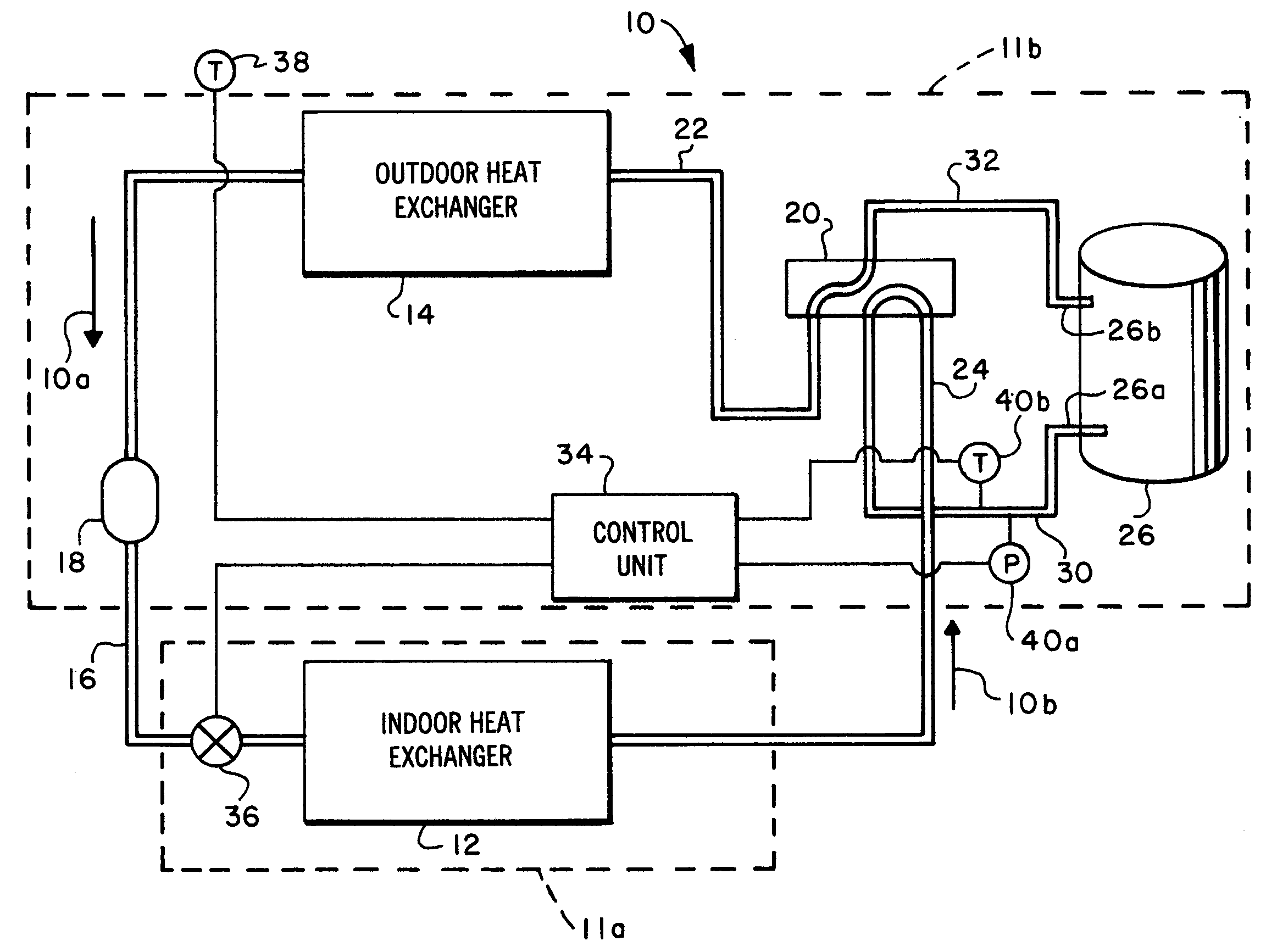
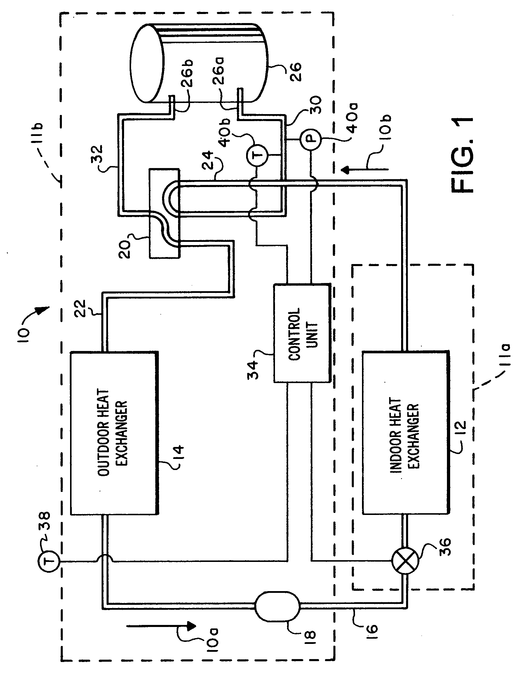
[0019]Referring to FIG. 1, there is illustrated a schematic diagram of an air conditioning apparatus or system, generally designated by the numeral 10. Apparatus 10 may be configured as a so-called heat pump or a reversible air conditioning apparatus which is operable to provide both cooling of an enclosed space and heating of the space. In the configuration of the apparatus or system 10, it is operating as a so-called air conditioner or in a cooling mode, and includes a so-called indoor unit 11a in communication with an enclosed space, not shown, for which air is circulated by a motor driven fan, also not shown, and in contact with an indoor heat exchanger or indoor coil 12.

[0020]The apparatus 10 also includes an outd...


PUM


Abstract

A vapor compression air conditioning system includes a motor operated expansion valve and control unit including sensors for determining the amount of superheat of the working fluid at or adjacent to the compressor inlet. Expansion valve position is adjusted to maintain a predetermined amount of superheat. The sensors may sense working fluid evaporator temperature and temperature downstream of the evaporator. Dual motor operated expansion valves may be disposed in the working fluid conduit between the heat exchangers in a reversible system. In operation, the expansion valve position may be set as a function of ambient temperature, a previous position, and predetermined superheat requirements to minimize liquid ingestion by the compressor.

Description

BACKGROUND OF THE INVENTION[0001]In the art of vapor compression type heating, ventilating and air conditioning (HVAC) equipment, there has been a continuing need to provide a suitable expansion device which may be reliably controlled to minimize the chance of damage to the system compressor resulting from liquid working fluid entering the compressor, maintain the ability during steady state operation to adjust working fluid flow to meet system requirements and to otherwise protect the compressor from damage during system shutdown or during periods of continuous low compressor suction pressure or a low super-heat condition of the working fluid.[0002]Although prior efforts have been made to provide so-called motorized or power operated expansion valve devices in commercial sizes of air conditioning equipment, such devices and associated controls have not been economically practical, reliable in operation, nor able to provide suitable control over refrigerant fluid flow to control sup...

Claims


Application Information

Patent Timeline
Patent Type & Authority Applications(United States)
IPC IPC(8): F25B41/04F25B41/06
CPCF25B13/00F25B41/062F25B2341/065F25B2500/26F25B2500/27F25B2500/28Y02B30/72F25B2600/21F25B2700/1933F25B2700/2106F25B2700/21151F25B2700/2117F25B2600/01F25B2313/005Y02B30/70F25B41/34F25B41/35
Inventor DOUGLAS, JONATHAN DAVID
Owner TRANE INT INC
Why Eureka
Try Eureka