
Light collection device

Inactive Publication Date: 2009-02-05
PRODISC TECH INC
View PDF1 Cites 60 Cited by
  • Summary
  • Abstract
  • Description
  • Claims
  • Application Information

AI Technical Summary

Benefits of technology

[0009]In view of the above, it is an object of the present invention to provide a light collection device that can minimize the problems of reflection, refraction and backscattering of the inputted light to thereby enhance the light collection efficiency of the light collection device.
[0011]As described above, the light collection device according to the present invention is provided with the fresnel lens unit while the light-incident surface thereof is coated with the anti-reflection layer to reduce reflection of light, so that the light enters the light-processing unit. Compared with conventional light collection devices, the light collection device according to the present invention has the advantages of reducing losses in the inputted light due to reflection or refraction, providing a better light condensation effect and enhancing light collection efficiency. Furthermore, a fresnel lens can be formed by injection molding or other molding techniques, which allows not only a variety of designs, but also mass production without requiring complex or precision manufacturing processes, thereby achieving lower production costs.

Problems solved by technology

However, conventional solar energy systems traditionally suffer from limitations such as requiring arrays that cover vast surface areas, and having low density and utilization rates.
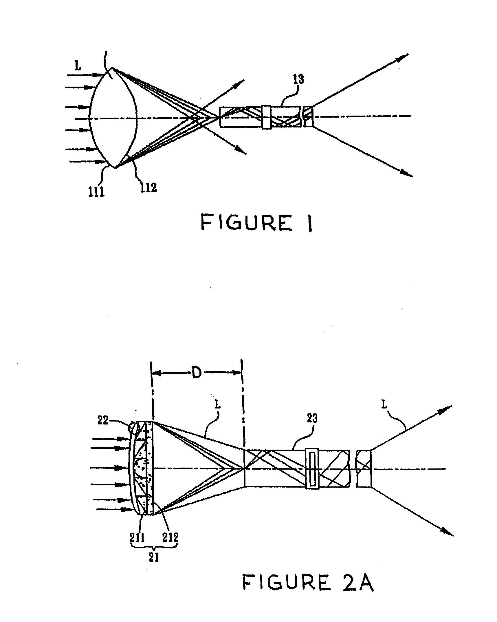
However, since the light collection lens unit 11 of the conventional light collection device 1 is composed of a convex lens structure which may have flaws in the lens itself, not all of the light energy passing through the lens will be perfectly concentrated and projected into the optical fiber cable 13.
In addition, conventional convex lenses for optical use are usually made of glass, and need to be ground and polished to form a desired shape, which can lead to high production costs, especially the more precise and complex is the process used to achieve the most ideal optical characteristics in the lens.

Method used


Image

  • Light collection device
  • Light collection device
  • Light collection device

Examples


Embodiment Construction

[0027]Light collection devices according to preferred embodiments of the present invention will now be described hereinbelow with reference to the accompanying drawings, wherein identical elements will be designated by the same reference numerals.

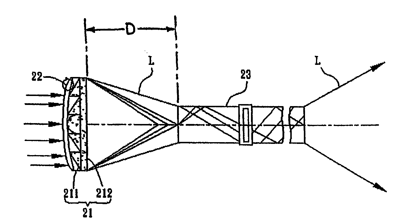
[0028]Referring to FIG. 2A, a light collection device 2 according to a first preferred embodiment of the present invention comprises a fresnel lens unit 21, an anti-reflection layer 22 and a light-processing unit 23. In this embodiment, the light collection device 2 is a solar concentrator configured to direct inputted solar energy or light onto a smaller specific spot or area.

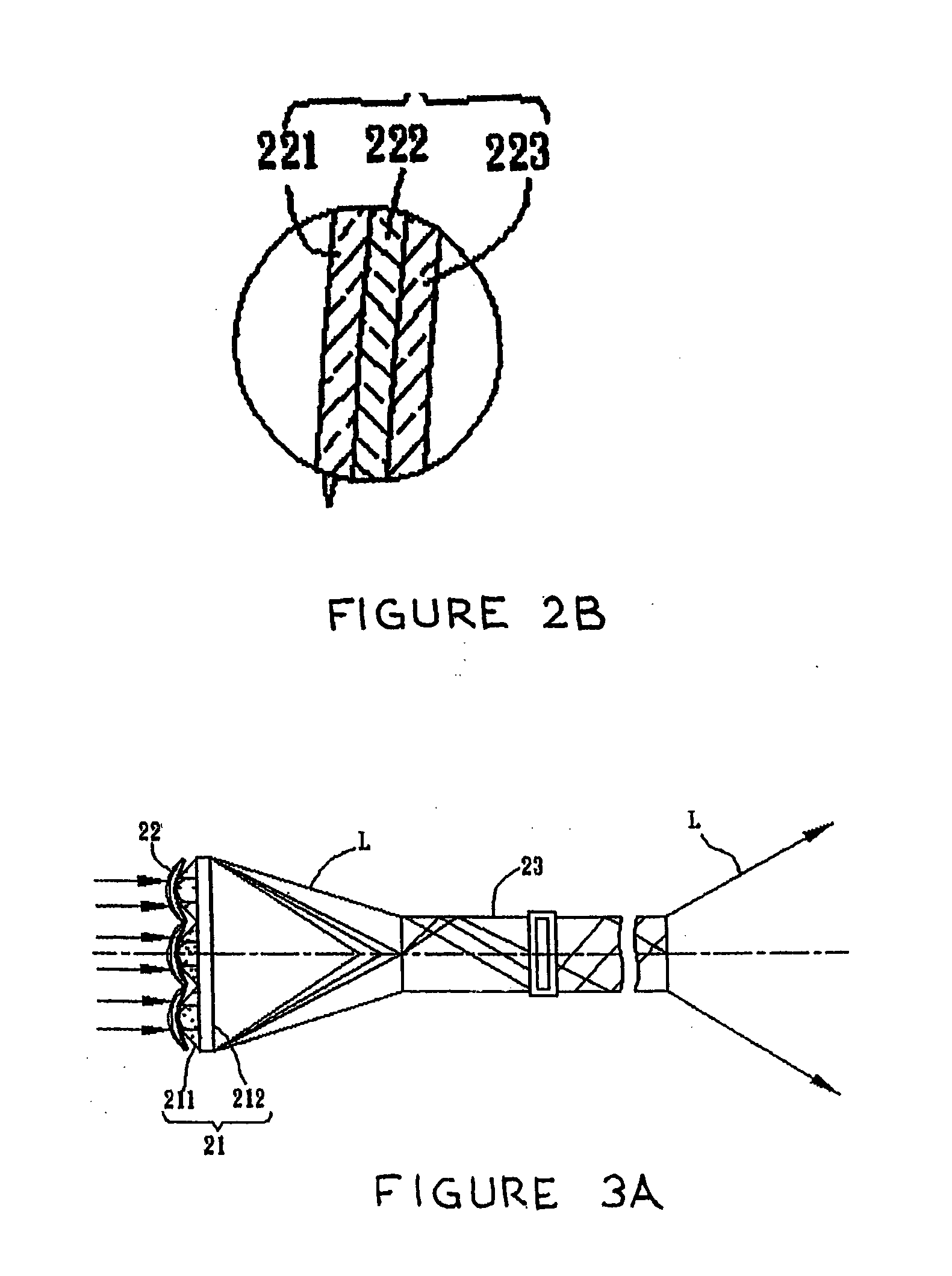
[0029]The fresnel lens unit 21 has a light-incident surface 211 and a light-emitting surface 212, wherein the light-incident surface 211 comprises at least one fresnel lens. More particularly, in terms of having different types of fresnel lens designs that are available, the light-incident surface 211 may comprise a single fresnel lens (see FIG. 2A), or an array consi...


PUM


Abstract

A light collection device assembled with a light-processing unit comprises a fresnel lens unit, an anti-reflection layer and a light-processing unit. The fresnel lens unit has a light-incident surface and a light-emitting surface. The light-processing unit is positioned with the light-emitting surface for transmitting or converting a light emitted from the fresnel lens unit. The anti-reflection layer is mounted or formed on the light-incident surface of the fresnel lens unit.

Description

BACKGROUND OF THE INVENTION[0001]1. Technical Field[0002]The present invention relates to a light collection device and, more particularly, to a light collection device that acts as a solar energy concentrator.[0003]2. Description of Related Art[0004]Solar energy is a natural, recyclable source of energy that can generate useful energy, such as electricity, through photoconversion. As solar energy is pollution-free, readily available and inexhaustible, it has become an important alternative energy source for human activities. However, conventional solar energy systems traditionally suffer from limitations such as requiring arrays that cover vast surface areas, and having low density and utilization rates. In addition, the efficiency of conventional solar energy systems in converting sunlight into electricity depends on numerous factors including but not limited to the materials used to construct the solar cells, the positioning of the solar array relative to the direction of the inc...

Claims


Application Information

Patent Timeline
IPC IPC(8): H01L31/0232F24J2/08G02B6/32F24S23/30F24S23/00
CPCF24J2/067F24J2/085F24J2/505G02B6/32H01L31/0547Y02E10/43Y02E10/52H01L31/0543G02B6/4298F24S80/52F24S23/12F24S23/31Y02E10/40
Inventor CHEN, HON-LUNTENG, KUO-HSINCHANG, HAN-YI
Owner PRODISC TECH INC
Learn More