
Throttle unit for dump bailer and method of blocking a water out zone in a production well utilizing the same

a technology of a well and a throttle unit, which is applied in the direction of flow control without auxiliaries, instruments, borehole/well accessories, etc., can solve the problems of poor cement bond at the well casing, adversely affecting the production at other zones, and conventional bridge plugs can only be mounted in the screen pipe, etc., to achieve good water blocking effect and facilitate complete curing

Inactive Publication Date: 2009-02-05
CPC CORPORATION
View PDF5 Cites 31 Cited by
  • Summary
  • Abstract
  • Description
  • Claims
  • Application Information

AI Technical Summary

Benefits of technology

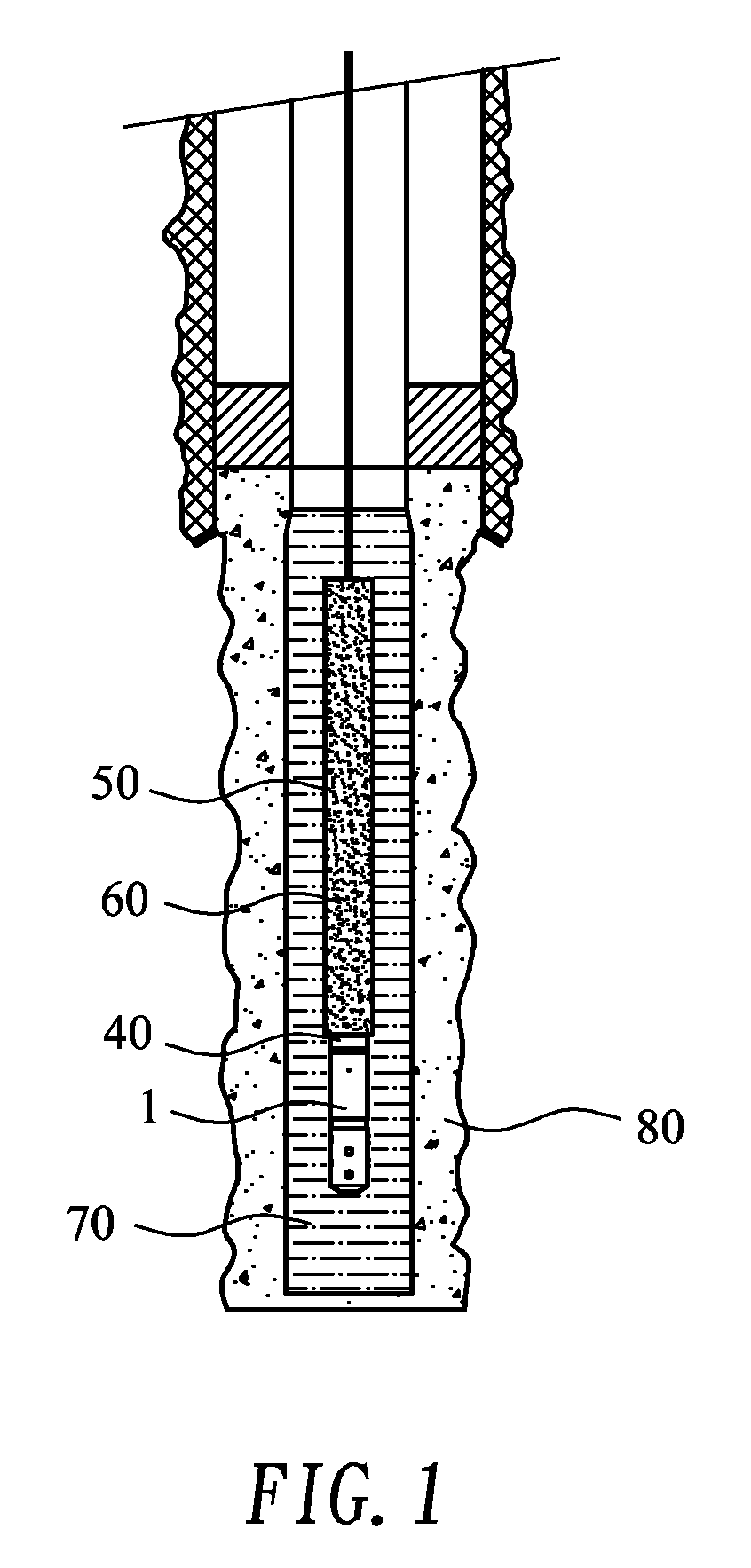
[0011]A primary object of the present invention is to provide a throttle unit for a dump bailer used in blocking a water out zone in a production well, so that water-blocking cement is released from the dump bailer via the throttle unit at a controlled rate to facilitate complete curing and good water blocking effect of the cement at the water out zone of the production well.
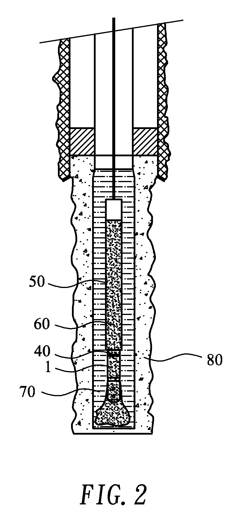
[0012]Another object of the present invention is to provide a method of blocking a water out zone in a production well by allowing cement to release from a pump bailer via a throttle unit, so that the cement could be accurately controlled at a preset flow rate to slowly permeate into a gravel layer of the production well and effectively block the water out zone.
[0013]To achieve the above and other objects, the method of the present invention for blocking a water out zone in a production well includes the steps of connecting a throttle unit to a lower end of a dump bailer; using an adjustable flowing space in the throttle unit to set a flow rate for a water-blocking fluid; loading the water-blocking fluid in the dump bailer; hanging the loaded dump bailer from an overhead work platform, and lowering the dump bailer to the water out zone; opening an outlet of the dump bailer when the dump bailer has been lowered to the water out zone, so that the water-blocking fluid in the dump bailer is released via the throttle unit at the preset flow rate to load up in the water out zone; allowing the water-blocking fluid to slowly permeate into a surrounding gravel layer in the well due to a difference in density between the water-blocking fluid and the gravel layer; and allowing the water-blocking fluid to reach an outer edge of the gravel layer and cure to thereby reliably block the water out zone.

Problems solved by technology

Generally, entering of water into a production well might be caused by different reasons, such as a high permeability formation at the production zone that results in an earlier edge encroachment on the well, vertical cracks or faults within the production zone that result in flowing of bottom formation water into the upper production zone, fissures on a casing or a plug set in the well, and poor cement bond at the casing of the well.
Under these conditions, the water must be completely shut off lest it should rise and enter the well to adversely affect the production at other zones.
In the case of a gravel packed production well subjected to water encroachment, since the gravels between a screen pipe and a wall of the well is highly permeable and there is not a casing provided at the production zone, both of the mechanical type bridge plug and the thermal expansion type patch flex are not applicable to block the perforated zone under the WGC for the purpose of continuing the oil / gas production of the well.
The conventional bridge plug can only be mounted in the screen pipe, and does not provide the function of blocking tiny meshes on the screen pipe and the gravels outside the screen pipe.
As to the conventional way of pumping gel into the gravel packed production well using coiled tubing, since the tiny meshes on the screen pipe and the gravels outside the screen pipe are highly permeable, the pumped gel would inevitably flow through the gravels and fails to completely enter a water out zone in the production well.
Regarding the way of placing traditional G-grade or H-grade cement milk at the well bottom to block the water out zone, it is also not applicable because the cement has large grain size and does not pass through the screen pipe into the gravels easily.
Therefore, once the bottom of the gravel packed production well is subjected to invasion by water, there is no way to save the well but leaving it to the rising water until the well is no longer economical for use and shut off, or until the invaded water accumulates in the oil pipe and the well no longer produces any oil or gas.
There is also limitation to the cement used to block water.
However, in the conventional way of releasing the cement from the dump bailer, it is not able to control a flow rate of the released cement.
Once a bottom opening of the dump bailer is opened, the cement in the dump bailer immediately flows out to mix with the formation water, resulting in an excessively low concentration of the cement and preventing the cement from curing effectively to thoroughly block the water out zone.
That is, the quickly released cement does not provide good water blocking effect and the formation water tends to rise via the incompletely filled pore spaces of the gravels to adversely affect the oil / gas production at other production zones.
When the cement milk is released at a high speed, the cement milk mixed with the formation water is highly diluted to the extent of being unable to cure and losing the function of blocking water.

Method used


Image

  • Throttle unit for dump bailer and method of blocking a water out zone in a production well utilizing the same
  • Throttle unit for dump bailer and method of blocking a water out zone in a production well utilizing the same
  • Throttle unit for dump bailer and method of blocking a water out zone in a production well utilizing the same

Examples


example 1

[0035]Use a dump bailer having an outer diameter of 1.52″ and an inner diameter of 1.456″. Keep the dump bailer still for 12 seconds. Three metric liters of cement is released at a flow rate of 1 liter / 4 seconds. A volume expansion rate of 18% is observed.

example 2

[0036]Use a dump bailer having an outer diameter of 1.52″ and an inner diameter of 1.456″. Keep the dump bailer still for 20 seconds. Three metric liters of cement is released at a flow rate of 1 liter / 6.67 seconds. A volume expansion rate of 14% is observed.

[0037]From the above examples, it is observed when the cement milk is slowly release data lower flow rate, the dilution extent of the cement milk is largely improved and the volume expansion rate of the cement is reduced, enabling the cement to have increased density and pressure resistance to ensure effective water blocking.

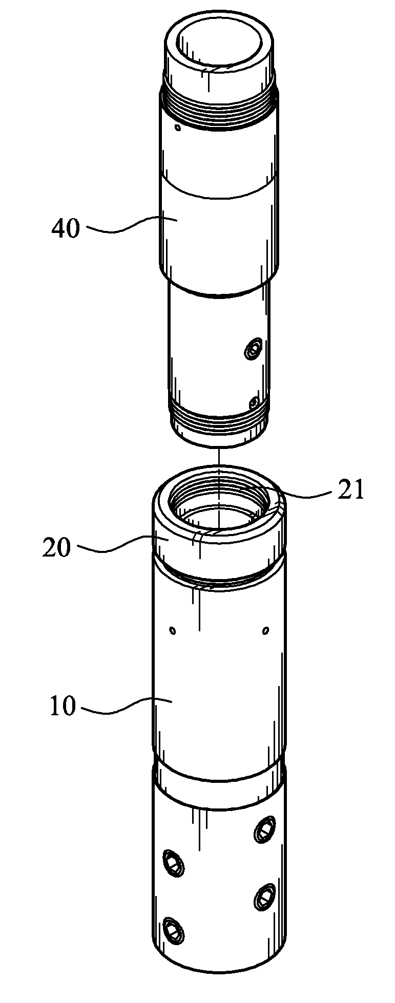
[0038]The present invention also provides a throttle unit 1 for connecting to a dump bailer 50 used in blocking a water out zone in a production well, so as to control a flow rate at which a predetermined water-blocking fluid in the dump bailer 50 is released via the throttle unit 1. Please refer to FIG. 5 that is an exploded perspective view of the throttle unit 1, and to FIGS. 6 and 7 that are assembled ve...


PUM


Abstract

A method of blocking a water out zone in a production well includes the steps of connecting a throttle unit to a dump bailer, wherein the throttle unit is internally defined a flowing space, which can be adjusted in size to thereby control a flow rate of cement for blocking the water out zone; loading the cement into the dump bailer; slowly lowering down the loaded dump bailer to the water out zone in the production well; opening an outlet of the dump bailer under control, so that the cement flows from the dump bailer into the throttle unit and is released at a flow rate preset by adjusting the size of the flowing space; allowing the released cement to load up in the water out zone and slowly permeate into a gravel layer in the production well before becoming cured to block the water out zone.

Description

FIELD OF THE INVENTION[0001]The present invention relates to a throttle unit for dump bailer and a method of blocking a water out zone in a production well utilizing the throttle unit; and more particularly, to a throttle unit mounted to a bottom of a dump bailer for controlling a flow rate of cement or liquid resin used to block a water out zone in an oil / gas production well to achieve complete and reliable water blocking effect.BACKGROUND OF THE INVENTION[0002]Gas, oil, and water coexist in the stratum of an oil / gas production well. Since gas and oil have specific gravities lower than that of water, they are floating on the water. When the oil / gas production reaches a certain volume, formation water would gradually rise to approach perforated zones in the well and tends to enter the production well.[0003]Generally, entering of water into a production well might be caused by different reasons, such as a high permeability formation at the production zone that results in an earlier e...

Claims


Application Information

Patent Timeline
IPC IPC(8): E21B27/02E21B33/13
CPCE21B27/02E21B34/105E21B33/138
Inventor SUN, CHI SANWU, CHIEN I.WU, CHIA SHUIFAN, LAI FUHHUANG, TE KUNFAN, CHEN HUI
Owner CPC CORPORATION
Learn More