Flow control system having an isolation device for preventing gas interference during downhole liquid removal operations

Inactive Publication Date: 2009-02-05
PINE TREE GAS
View PDF99 Cites 15 Cited by
  • Summary
  • Abstract
  • Description
  • Claims
  • Application Information

AI Technical Summary

Benefits of technology

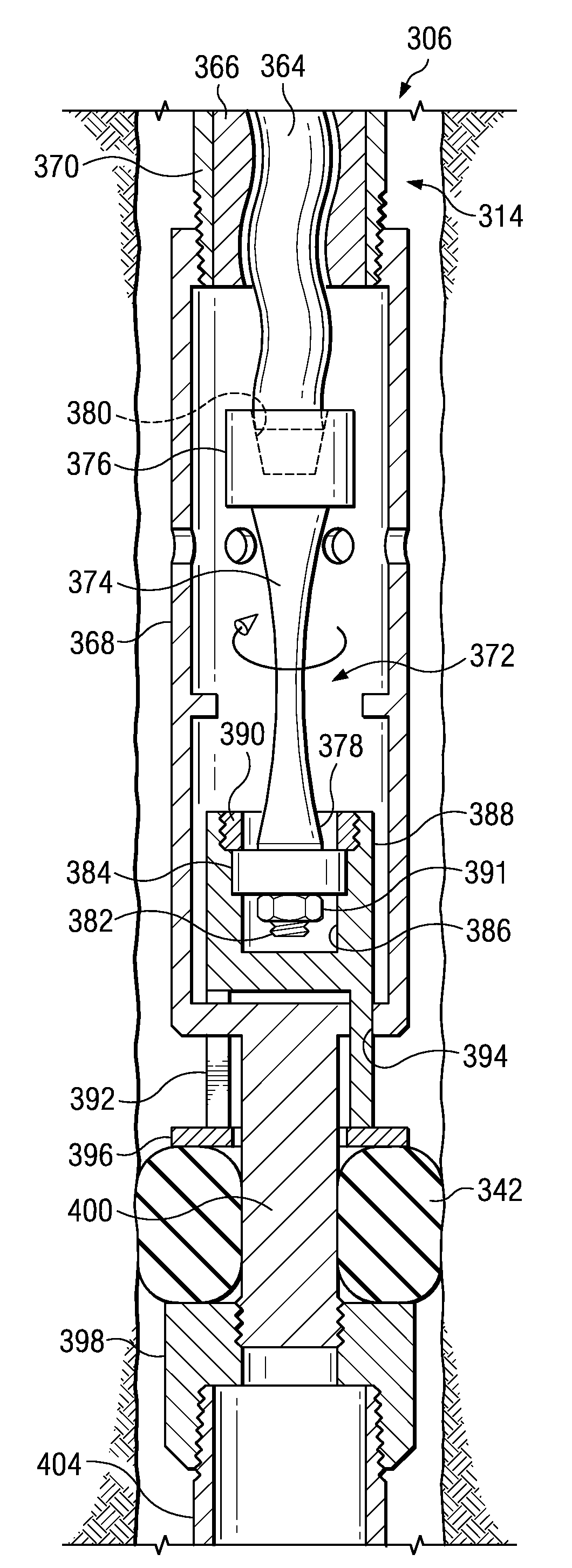
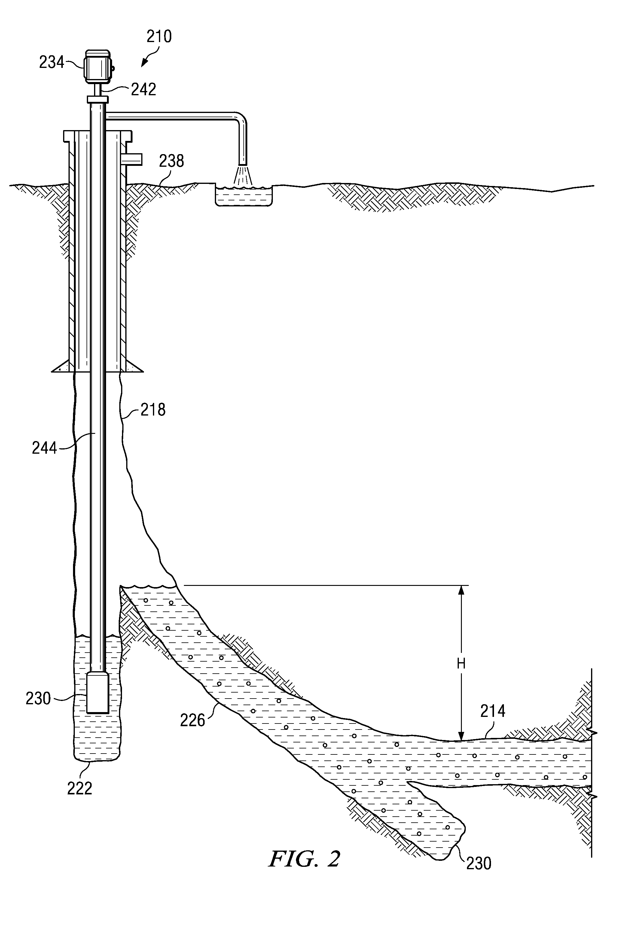
[0008]The problems presented in removing liquid from a gas-producing well are solved by the systems and methods of the illustrative embodiments described herein. In one embodiment, a flow control system is provided that includes a progressing cavity pump positioned in a wellbore. The progressing cavity pump includes a rotor that is received by a stator. The rotor rotates within the stator to remove liquid from the wellbore, and the rotor is capable of axial movement between a disengaged position, a first engaged position, and a second engaged position. A push rod is configured

Problems solved by technology

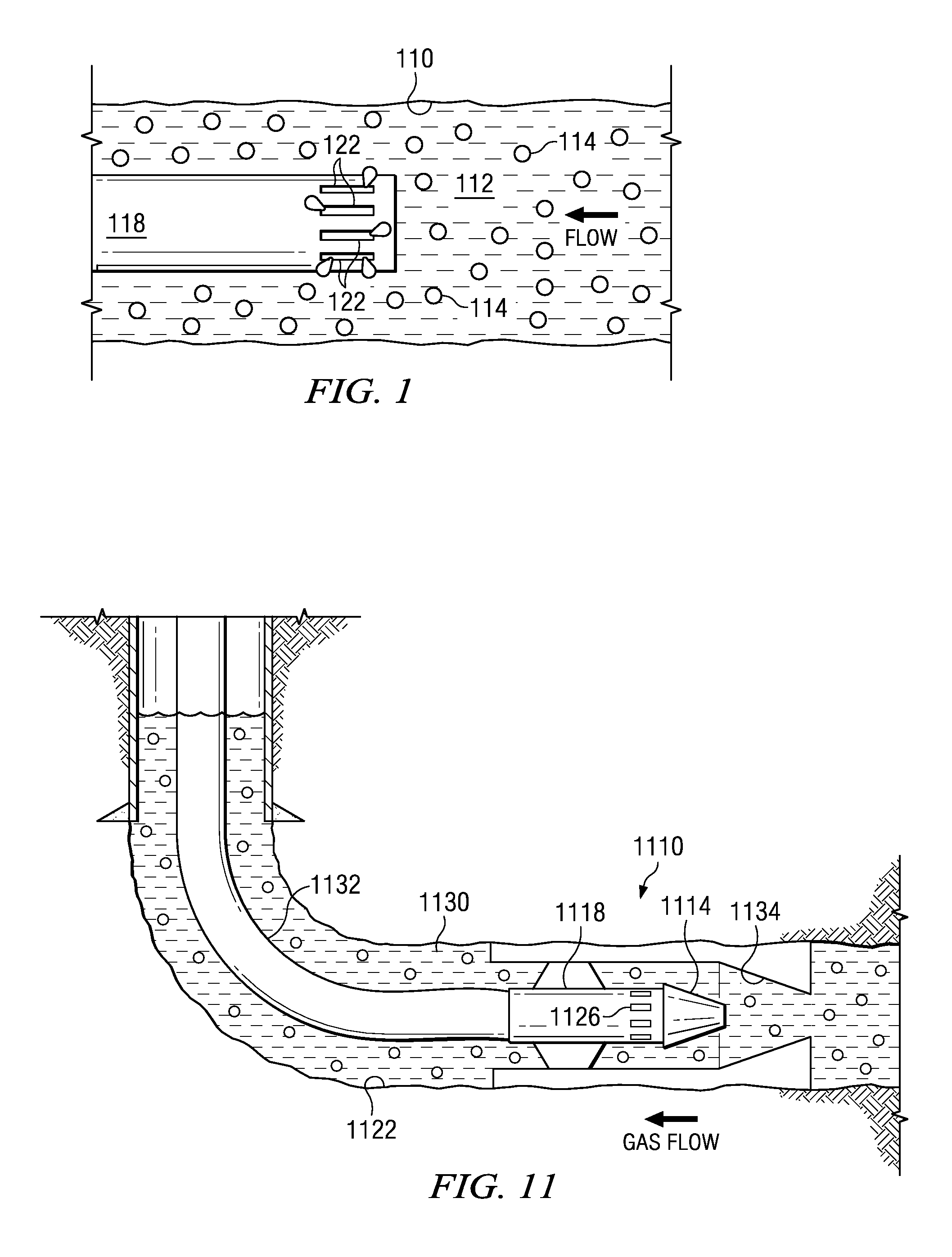
Gas interference is caused when gas, flowing into the suction of the pump, “interferes” with the volumetric efficiency of the pump.
When two-phase fluids enter a pump, the gas phase can displace an equivalent volume of liquid, thus causing inefficient volumetric pump efficiency.
Further problems can result from the compressible nature of the gas, resulting in “gas lock” of the pumping equipment.
In addition, due to the diminished flow of the lubricating and cooling liquid through the pump, increased frictional wear c

Method used


Image

  • Flow control system having an isolation device for preventing gas interference during downhole liquid removal operations
  • Flow control system having an isolation device for preventing gas interference during downhole liquid removal operations
  • Flow control system having an isolation device for preventing gas interference during downhole liquid removal operations

Examples


Embodiment Construction

[0038]In the following detailed description of several illustrative embodiments, reference is made to the accompanying drawings that form a part hereof, and in which is shown by way of illustration specific embodiments in which the invention may be practiced. These embodiments are described in sufficient detail to enable those skilled in the art to practice the invention, and it is understood that other embodiments may be utilized and that logical structural, mechanical, electrical, and chemical changes may be made without departing from the spirit or scope of the invention. To avoid detail not necessary to enable those skilled in the art to practice the embodiments described herein, the description may omit certain information known to those skilled in the art. The following detailed description is, therefore, not to be taken in a limiting sense, and the scope of the illustrative embodiments are defined only by the appended claims.

[0039]One method to overcome gas interference probl...


PUM


Abstract

A flow control system includes a pump positioned in a wellbore to remove liquid from the wellbore. An isolation device is positioned downhole of the pump and is expandable within the wellbore between a sealed position and an unsealed position. The isolation device in the sealed position substantially reduces gas flow at the pump during removal of the liquid.

Description

CROSS-REFERENCE TO RELATED APPLICATIONS[0001]This application claims the benefit of U.S. Provisional Application No. 60 / 963,337, filed Aug. 3, 2007, and U.S. Provisional Application No. 61 / 002,419, filed Nov. 1, 2007, both of which are hereby incorporated by reference.BACKGROUND[0002]1. Field of the Invention[0003]The invention relates generally to the recovery of subterranean deposits and more specifically to methods and systems for controlling the accumulation of liquids in a well.[0004]2. Description of Related Art[0005]Gas wells, especially those in which coal-bed methane is produced, may experience large influxes of water downhole that must be removed by pumping to ensure adequate gas production. The pumping system must be designed to assure the pump can effectively remove the produced water from the well. One design criteria recognizes the issue of gas interference. Gas interference is caused when gas, flowing into the suction of the pump, “interferes” with the volumetric effi...

Claims


Application Information

Patent Timeline
IPC IPC(8): E21B33/128E21B43/12
CPCE21B33/128E21B43/126F04C2/1073F04C2240/811F04C13/008F04C15/0065F04C15/0076F04C13/007
Inventor ZUPANICK, JOSEPH A.
Owner PINE TREE GAS
Why Eureka
Try Eureka