Flow switch and container

Inactive Publication Date: 2009-02-05
AXIAL TECH
View PDF25 Cites 22 Cited by
  • Summary
  • Abstract
  • Description
  • Claims
  • Application Information

AI Technical Summary

Benefits of technology

[0179]It is further envisioned that the valve can include a mechanism associated with the valve housing for

Problems solved by technology

Several disadvantages are associated with this type of ball valve.
For example, the extension of an actuator from the sidewall of the valve is cumbersome and not desirable for applications where space limitations and physical access to the actuator are a concern.
When such a valv

Method used


Image

  • Flow switch and container
  • Flow switch and container
  • Flow switch and container

Examples


Embodiment Construction

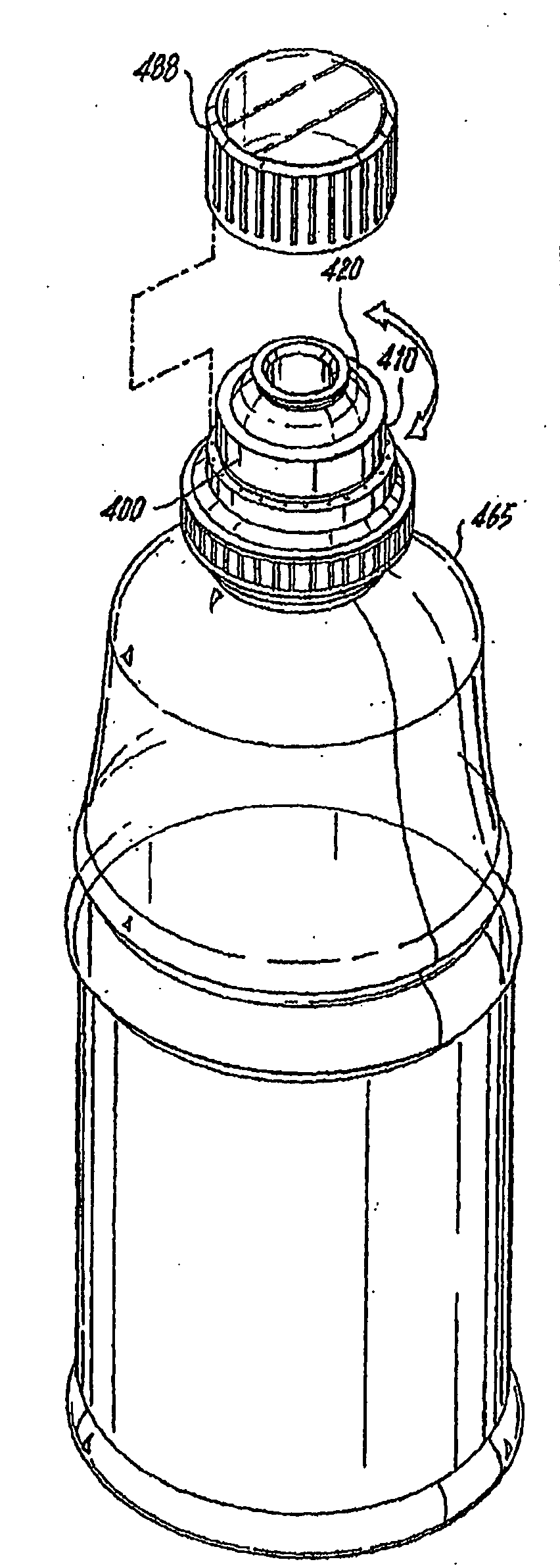
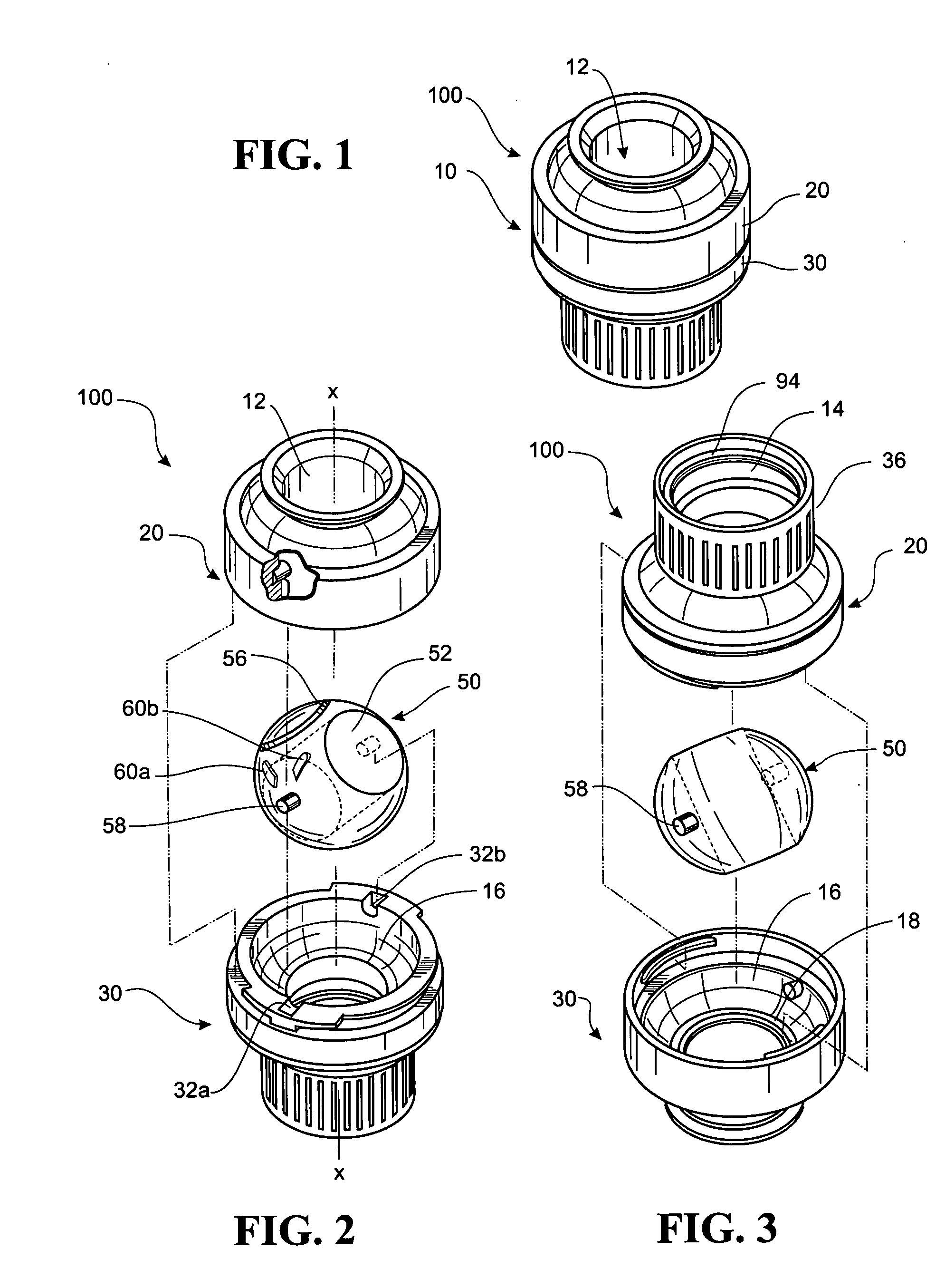
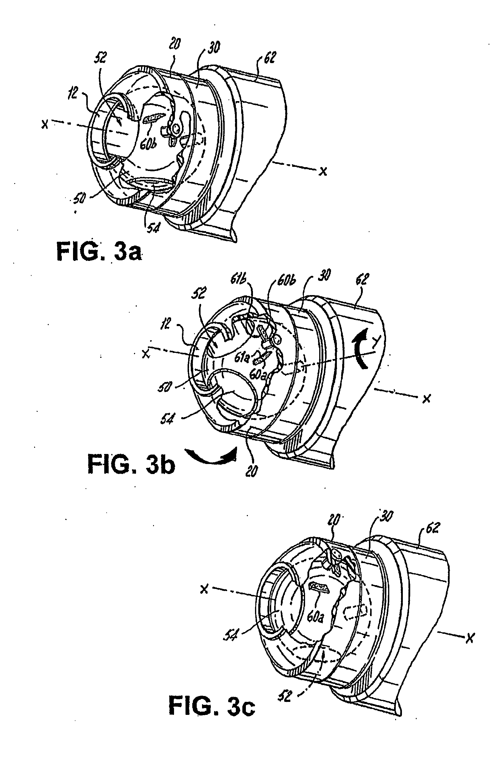
[0270]Referring now to FIGS. 1-19, wherein like reference numerals identify similar structural elements or features of the subject invention, there is illustrated in FIG. 1 a valve assembly in accordance with the present invention and designated generally by reference number 100. Valve assembly 100 is adapted for use in a variety of applications, such as for example, medical, consumer beverage, pharmaceutical containers, automobile, household appliance and marine. Valve 100 includes, inter alia, a valve housing 10 having an upper body portion 20 and a lower body portion 30 and a generally spherical valve member 50. The upper and lower body portions 20 / 30 of the housing 10 define an internal chamber 16 for accommodating the valve member 50 and a central axis “X” for the valve. The housing 10 also has axially aligned inlet and outlet ports, 12 and 14 respectively, formed in the upper and lower body portions, 20 and 30 respectively.

[0271]The generally spherical valve member 50 is seate...


PUM


Abstract

A flow switch assembly which includes a valve housing that includes an upper body portion and a lower body portion that are rotatably engaged relative each other. The upper and lower body portions define a chamber. The housing includes an inlet and outlet to the chamber. A valve member seated in the chamber of the valve housing for movement between an open position establishing at least one passage between the inlet and the outlet and a closed position wherein the at least one passage between the inlet and the outlet is non-established. Interactive cam elements are associated with at least one of the upper body portion and the lower body portion, and associated with the valve member, are provided for moving the valve member between the open position and the closed position when the upper body portion of the housing is rotated relative to the lower body portion.

Description

CROSS REFERENCE TO RELATED APPLICATIONS[0001]This application is a continuation-in-part of U.S. application Ser. No. 11 / 640,009 filed Dec. 15, 2006 and further claims priority from U.S. application Ser. No. 11 / 413,741 filed Apr. 28, 2006, which in itself claims priority from U.S. Provisional Patent Application Ser. No. 60 / 675,668 filed Apr. 28, 2005; and the subject application further claims the benefit of priority from U.S. Provisional Patent Application Ser. No. 60 / 818,825 filed Jul. 6, 2006, the disclosures of each of said applications are herein incorporated by reference in their entireties.FIELD OF THE INVENTION[0002]The present invention relates to a flow switch. Specifically although not solely the present invention relates to a flow switch for or of a consumer beverage container such as a beverage or water bottle, that incorporates the switch at the spout end of the container to control the dispensing of liquid from the container.[0003]Specifically although not solely the p...

Claims


Application Information

Patent Timeline
IPC IPC(8): B65D43/26F16K5/00
CPCA47G19/2266A61F5/4405B60K15/0406B65D47/06B65D47/266F16K37/0008B67D7/0294F16K5/0647F16K31/52458F16K31/5284B65D51/28
Inventor KESSELL, MICHAEL R.ADAMS, PAUL NEVILLEWEIR, STEVEN L.BOLANOS, HENRY
Owner AXIAL TECH
Why Eureka
Try Eureka