Cooling systems for power semiconductor devices

a technology of cooling system and power semiconductor, applied in semiconductor devices, semiconductor/solid-state device details, lighting and heating apparatus, etc., can solve the problems of affecting the cooling effect of power semiconductor devices, and generating excess heat during operation

Inactive Publication Date: 2009-02-05
GM GLOBAL TECH OPERATIONS LLC
View PDF2 Cites 72 Cited by
  • Summary
  • Abstract
  • Description
  • Claims
  • Application Information

AI Technical Summary

Benefits of technology

[0007]In accordance with an exemplary embodiment, a cooling device is provided for liquid cooling a power semiconductor device. The device includes a coolant diverter for guiding liquid coolant to the power semiconductor device. The coolant diverter has a first plate for dividing the coolant diverter into a first cavity and a second cavity. The second cavity positioned adjacent the power semiconductor device. The first plate further includes an opening to fluidly couple the first cavity with the second cavity such that the liquid coolant flows into the first cavity, through the opening in the first plate, and into the second cavity to cool the power semiconductor device. The first cavity has a cross-sectional area that generally decreases in a downstream direction, and the second cavity has a cross-sectional area that generally increases in the downstream direction.

Problems solved by technology

These semiconductor devices may generate excess heat during operation.
These fluctuations in power demand can cause temperature changes in the semiconductor devices connected to the traction motors, which may result in degradation from the heat itself or from variations in the coefficients of expansion between the constituent materials.
Conventional cooling systems may not adequately cool the power semiconductor devices in all situations.
Particularly, conventional cooling systems may be unable to properly direct coolant to certain areas, including those areas that may be in greatest need of additional cooling.
This can be a result of the inability to direct fresh coolant to the various portions of the semiconductor devices or the presence of intervening layers such as interconnects and insulating layers.
Additionally, many conventional cooling systems can be difficult to manufacture, overly-complicated, and expensive.

Method used


Image

  • Cooling systems for power semiconductor devices
  • Cooling systems for power semiconductor devices
  • Cooling systems for power semiconductor devices

Examples


Embodiment Construction

[0014]The following detailed description is merely exemplary in nature and is not intended to limit the invention or the application and uses of the invention. Furthermore, there is no intention to be bound by any expressed or implied theory presented in the preceding technical field, background, brief summary or the following detailed description.

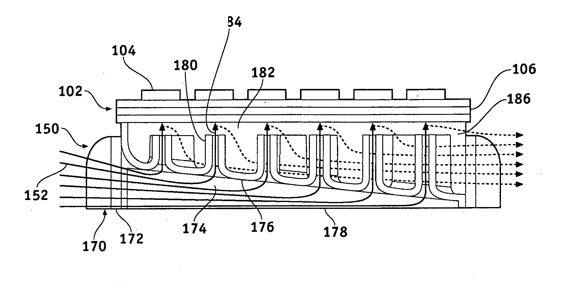
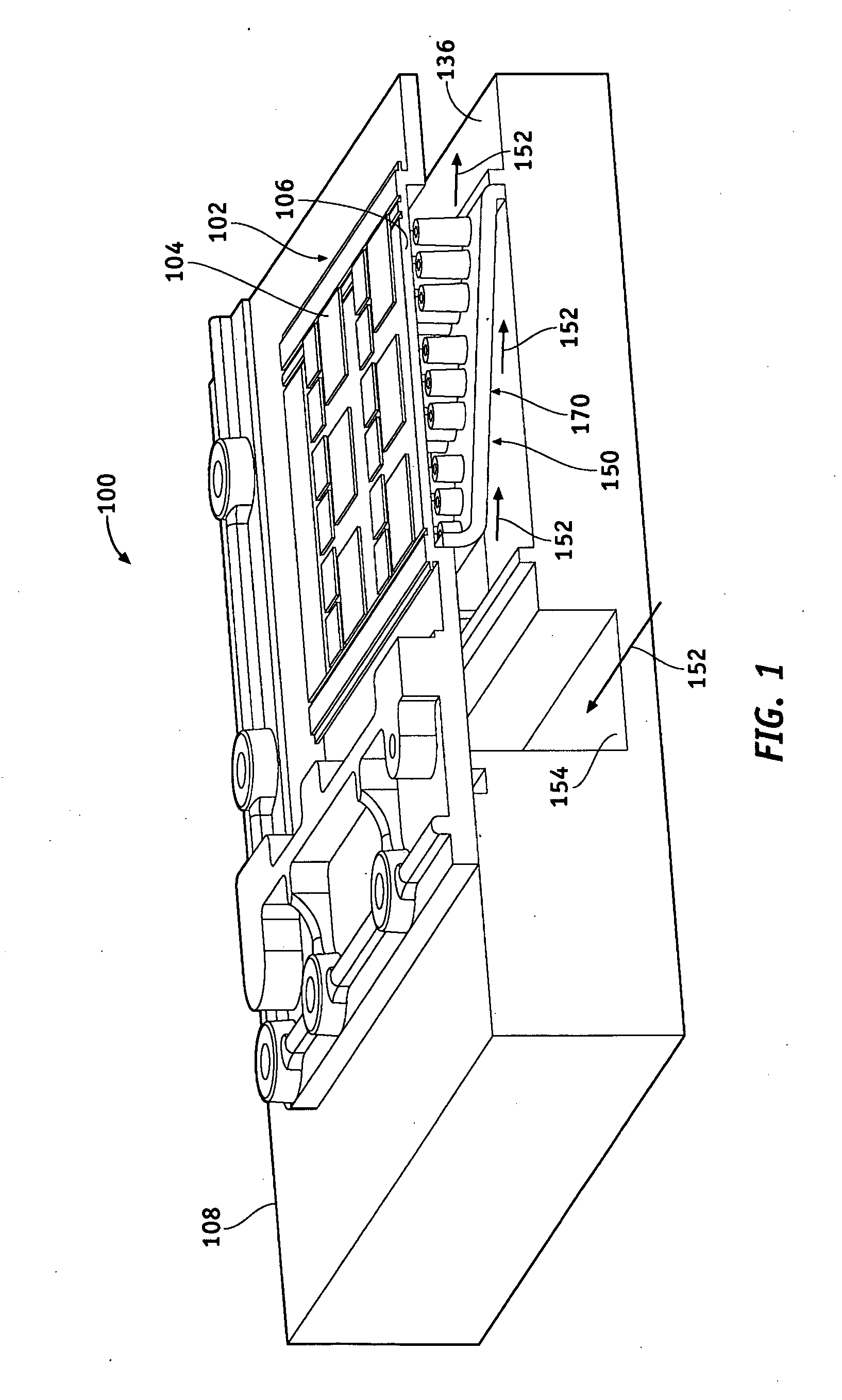
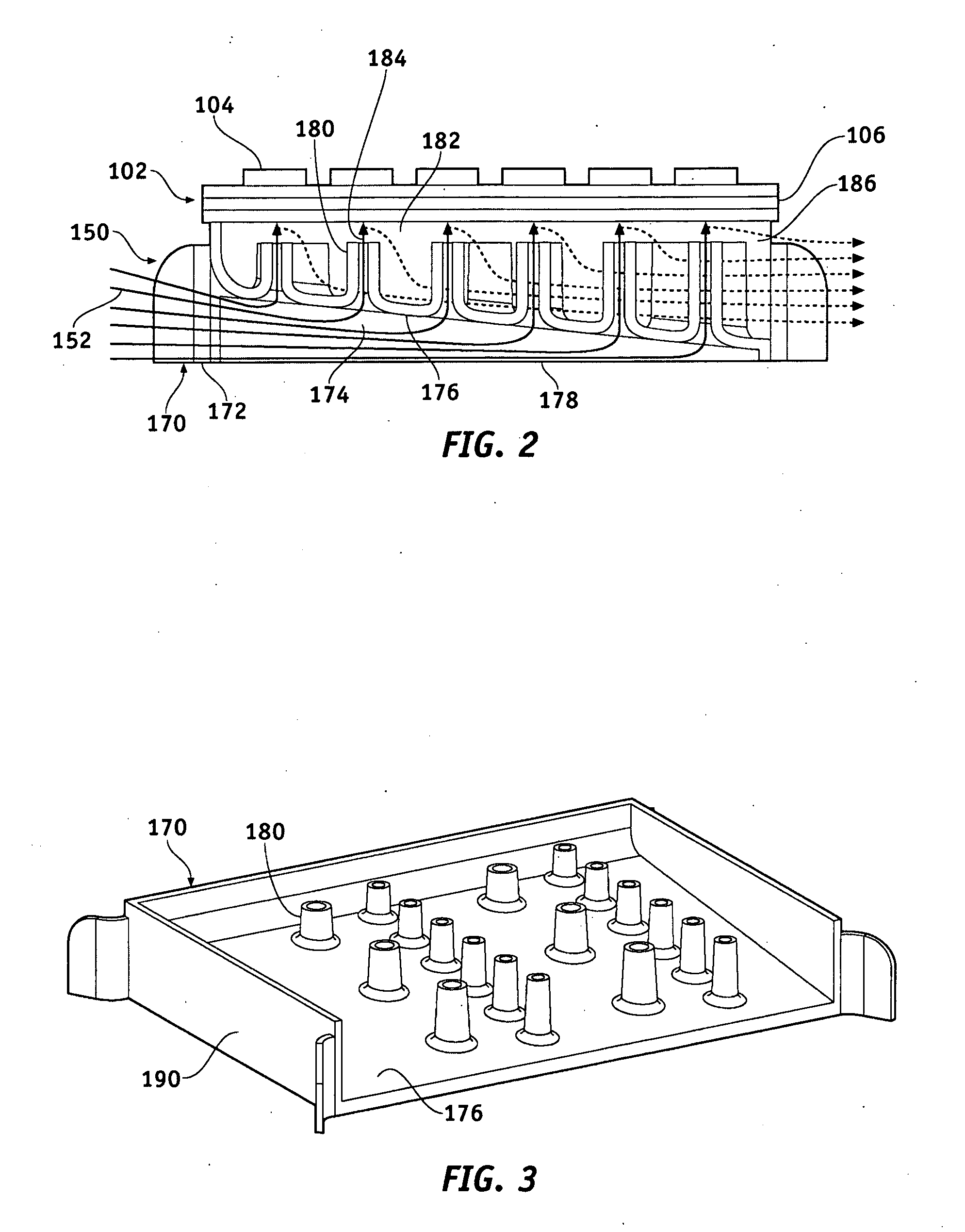
[0015]Broadly, exemplary embodiments disclosed herein include cooling systems for semiconductor devices in power modules. More specifically, exemplary embodiments of the cooling systems include a coolant diverter that is wedge-shaped such that coolant is evenly distributed across the nozzles.

[0016]FIG. 1 is a partial, isometric cross-sectional view of a power module 100 in accordance with an exemplary embodiment. The power module 100 is suitable for use on an electric or hybrid vehicle, for example, with a three-phase, alternating current (AC) electric motor. The power module 100 includes one or more semiconductor devices 102 arranged with...


PUM


Abstract

A cooling device is provided for liquid cooling a power semiconductor device. The device includes a coolant diverter for guiding liquid coolant to the power semiconductor device. The coolant diverter has a first plate for dividing the coolant diverter into a first cavity and a second cavity. The second cavity positioned adjacent the power semiconductor device. The first plate further includes an opening to fluidly couple the first cavity with the second cavity such that the liquid coolant flows into the first cavity, through the opening in the first plate, and into the second cavity to cool the power semiconductor device. The first cavity has a cross-sectional area that generally decreases in a downstream direction, and the second cavity has a cross-sectional area that generally increases in the downstream direction.

Description

CROSS REFERENCE TO RELATED APPLICATIONS[0001]This application claims the benefit of U.S. Provisional Application No. 60 / 952,743, filed Jul. 30, 2007, which is incorporated herein by reference in its entirety.TECHNICAL FIELD[0002]The present invention generally relates to cooling systems for power semiconductor devices, and more particularly relates to coolant diverters for direct jet impingement cooling of the substrates associated with power semiconductor devices.BACKGROUND OF THE INVENTION[0003]Semiconductor devices are commonly utilized as switches or rectifiers in high-power electric circuits. As one example, power inverters are used in electric and hybrid electric vehicles to provide three phase operating power to the electric drive motor of the vehicle. These semiconductor devices may generate excess heat during operation. For example, the power demands of electric traction motors may fluctuate over a wide range. These fluctuations in power demand can cause temperature changes...

Claims


Application Information

Patent Timeline
Patent Type & Authority Applications(United States)
IPC IPC(8): H01L23/34F28F7/00
CPCH01L23/4735H01L2924/0002H01L2924/00
Inventor MANN, BROOKS S.WOODY, GEORGE R.WARD, TERENCE G.NELSON, DAVID F.
Owner GM GLOBAL TECH OPERATIONS LLC
Why Eureka
Try Eureka