
Sheet processing apparatus and sheet processing method

a technology of processing apparatus and sheet, which is applied in the direction of registering device, thin material processing, article separation, etc., can solve the problems of too late driving up to the detection position, inability to increase the conveying speed and improve the performance, and achieve the effect of speeding up the punching process and improving performan

Active Publication Date: 2009-02-05
KK TOSHIBA +1
View PDF6 Cites 28 Cited by
  • Summary
  • Abstract
  • Description
  • Claims
  • Application Information

AI Technical Summary

Benefits of technology

[0009]The present invention is intended to provide a sheet processing apparatus and s sheet processing method to speed up the punching process and improving the performance.
[0011]Furthermore, to accomplish the above object, in an embodiment, there is provided a processing method of a sheet processing apparatus including a first detector configured to detect a leading edge of a sheet conveyed in a conveying direction, a second detector provided on a downstream side of the first detector in the sheet conveying direction to detect the leading edge of the sheet conveyed, a punching portion, on the downstream side of the first detector in the sheet conveying direction, to move in a sheet width direction crossing the sheet conveying direction and perform a punching process for the sheet, and an edge detector configured to move in the width direction together with the punching portion and detect the edge of the sheet conveyed in the width direction, comprising judging whether the edge detector can detect the edge of the sheet or not on the basis of at least either of information of a conveying speed of the sheet and a sheet length in the conveying direction, when the edge detector starts movement in the width direction after the first or second detector detects the leading edge of the sheet; selecting the detector positioned on the most downstream side in the conveying direction among the usable first and second detectors on the basis of a result of the judgment; and permitting the edge detector to start movement and to detect the edge of the sheet when the selected first or second detector detects the leading edge of the sheet conveyed.

Problems solved by technology

Therefore, if the conveying speed is increased to improve the processing performance, a problem arises that the driving up to the detection position is too late.
Therefore, the time until the position for detecting the lateral edge of the sheet becomes longer, so that as the sheet size in the width direction becomes smaller, it is impossible to increase the conveying speed and improve the performance.

Method used


Image

  • Sheet processing apparatus and sheet processing method
  • Sheet processing apparatus and sheet processing method
  • Sheet processing apparatus and sheet processing method

Examples


first embodiment

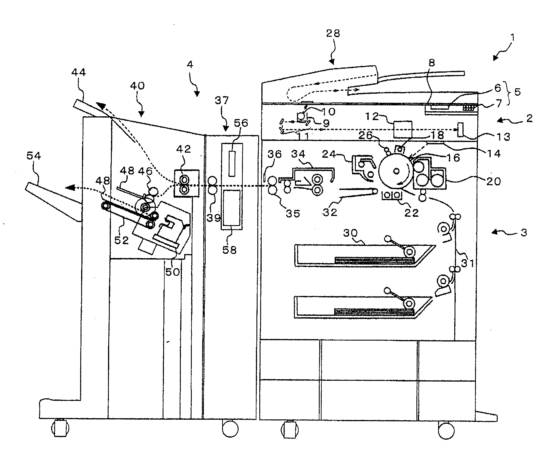
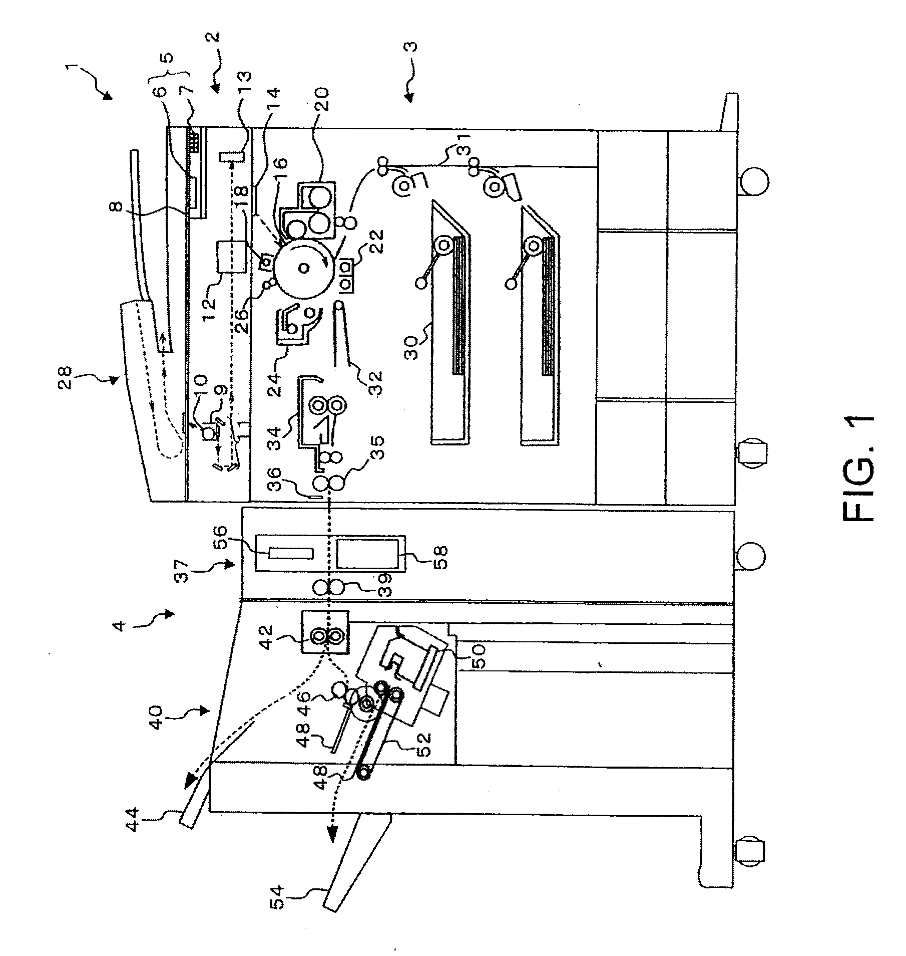
[0023]FIG. 1 is a schematic view of the image forming apparatus having the sheet processing apparatus.

[0024]An image forming apparatus 1 includes an image reading portion 2 for reading an image to be read and an image forming portion 3 for forming an image. On the upper part of the image forming apparatus 1, an operation panel 5 including a display 6 of a touch panel type and various operation keys is installed.

[0025]The operation keys 7 of the operation panel 5 has, for example, ten keys, a reset key, a stop key, and a start key. On the display 6, the sheet size, the number of copies, and various processes such as the punching process are displayed and input.

[0026]The image reading portion 2 includes a transmissible original table 8, a carriage 9, an exposure lamp 10, a reflection mirror 11, an imaging lens 12 to converge reflected light, and a CCD 13 (charge coupled device) to fetch the reflected light and convert image information to an analog signal.

[0027]The image forming porti...

third embodiment

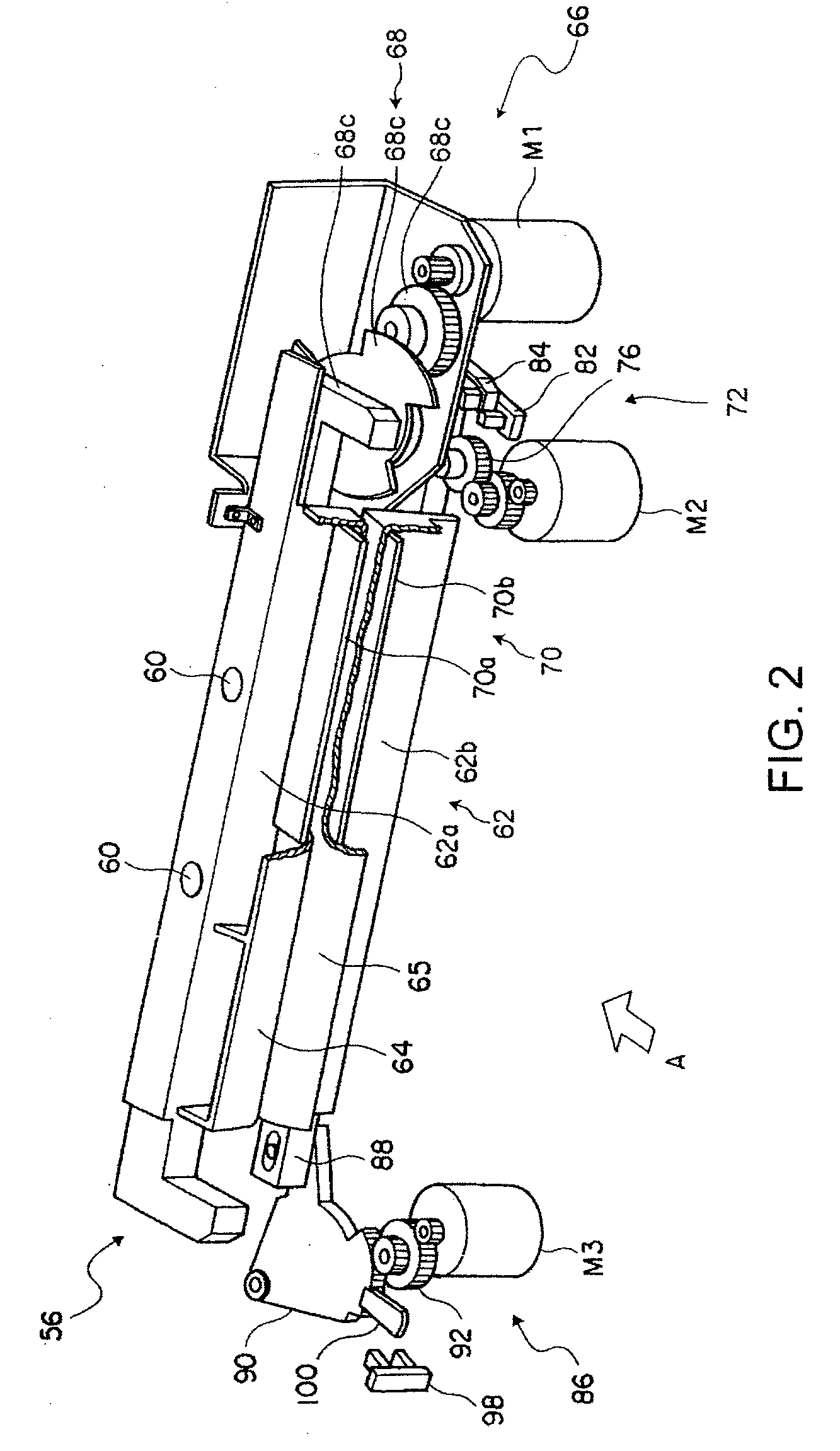
[0118]FIGS. 10A to 10C are schematic views for explaining another example of the punching portion 62. Hereinafter, to the same parts as those indicated in the embodiments aforementioned, the same numerals are assigned and only the characteristic parts of this embodiment will be explained.

[0119]As shown in FIG. 10A, in the punch unit 56, after the punching portion 62 is stopped at the punching position, the punch heads 60 punch sheets. Further, the punch heads 60 obtain power from the DC motor M1 of the driving portion 66 and the power transmission member 68c moves alternately in the directions of the arrows I and J, thereby moves up and down and drives to punch the surface of each sheet.

[0120]If a jam occurs when the punch heads 60 are moved down, the punch portion 37 of the sheet finishing apparatus 4, to cancel the jam, must open the main body and rotate the punch unit 56 in the direction of the arrow K at a fulcrum of the rotary shaft 120. However, in the punch portion 37, the fi...


PUM

PropertyMeasurementUnit
Lengthaaaaaaaaaa
Widthaaaaaaaaaa

Abstract

A sheet processing apparatus includes a first detector configured to detect a leading edge of a sheet conveyed in a conveying direction, a second detector provided on a downstream side of the first detector in the sheet conveying direction to detect the leading edge of the sheet conveyed, a punching portion, in the downstream side of the first detector in the sheet conveying direction, to move in a sheet width direction crossing the sheet conveying direction and perform a punching process for the sheet, an edge detector configured to move in the width direction together with the punching portion and detect the edge of the sheet conveyed in the width direction, and a controller, on the basis of at least either of information of a conveying speed of the sheet and a sheet length in the conveying direction, when the edge detector starts movement in the width direction after the first or second detector detects the leading edge of the sheet, to judge whether the edge detector can detect the edge of the sheet or not, as a result of the judgment, selecting the detector positioned on the most downstream side in the conveying direction among the first and second detectors which can be used, and when the selected first or second detector detects the leading edge of the sheet conveyed, permitting the edge detector to start movement to detect the edge of the sheet in the width direction.

Description

CROSS-REFERENCE TO RELATED APPLICATION[0001]This application is based upon and claims the benefit of priority from the prior U.S. Patent Application No. 60 / 952,838, filed on Jul. 30, 2007; the entire contents of all of which are incorporated herein by reference.[0002]This application is based upon and claims the benefit of priority from the prior U.S. Patent Application No. 60 / 968,544, filed on Aug. 28, 2007; the entire contents of all of which are incorporated herein by reference.[0003]This application is based upon and claims the benefit of priority from the prior U.S. Patent Application No. 60 / 968,851, filed on Aug. 29, 2007; the entire contents of all of which are incorporated herein by reference.[0004]This application is based upon and claims the benefit of priority from the prior Japanese Patent Application No. 2008-66001, filed on Mar. 14, 2008; the entire contents of all of which are incorporated herein by reference.FIELD OF THE INVENTION[0005]The present invention relates t...

Claims


Application Information

Patent Timeline
IPC IPC(8): B65H7/02
CPCB65H9/10B65H35/0006B65H2301/5152B65H2511/514B65H2513/511B65H2801/27B65H2701/1311B65H2701/1315B65H2220/01Y10T83/04Y10T83/527B65H2513/51
Inventor YAHATA, ISAOIGUCHI, KENYADA, KOUICHIROU
Owner KK TOSHIBA
Learn More