Motor-driven implement having switchable summer-winter operating function

a technology of motor-driven implements and summer-winter operation, which is applied in the direction of mechanical equipment, machines/engines, combustion-air/fuel-air treatment, etc., can solve the problems of not giving the possibility of severe cooling of the cylinder through the closure element, and it is possible to deflect the air over the cylinder. , to achieve the effect of high ram pressur

Inactive Publication Date: 2012-05-31
MAKITA CORP
View PDF0 Cites 0 Cited by
  • Summary
  • Abstract
  • Description
  • Claims
  • Application Information

AI Technical Summary

Benefits of technology

[0013]According to a further advantageous embodiment of the motor-driven implement, a spark plug can be provided in the area of the upper part of the cylinder, where the warm air opening is disposed in the area of the spark plug, preferably in the area 10 mm above the upper dead point of a piston guided in the cylinder and particularly preferably in the area of cooling ribs disposed on the upper side of the cylinder. A particularly advantageous ventilation of the carburettor chamber with warm air is thus made possible since in the said region a particularly high ram pressure prevails between the upper part of the cylinder and a housing encasing the cylinder. As a result of the high ram pressure on the engine compartment side of the intermediate wall, a particularly strong air flow through the warm air opening into the carburettor chamber is rendered possible.

Problems solved by technology

However, the disadvantage arises that it is certainly possible to deflect the air over the cylinder but this cannot be introduced as heated air into the carburettor chamber in order to operate the carburettor with heated air at low outside temperatures.
The fraction of air guided over the cylinder for cooling can certainly be varied by means of the closure element but for example, no possibility is given for providing by means of the closure element a severe cooling of the cylinder whilst simultaneously supplying cold air into the carburettor chamber, for example, for summer operation of the motor-driven implement at high outside temperatures.

Method used


Image

  • Motor-driven implement having switchable summer-winter operating function
  • Motor-driven implement having switchable summer-winter operating function
  • Motor-driven implement having switchable summer-winter operating function

Examples


Embodiment Construction

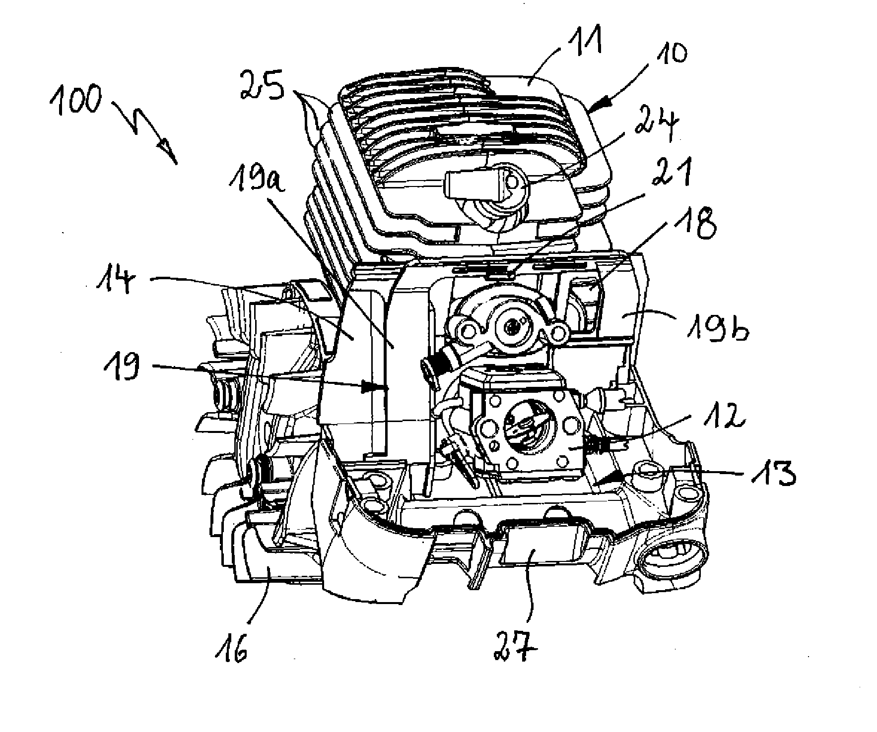
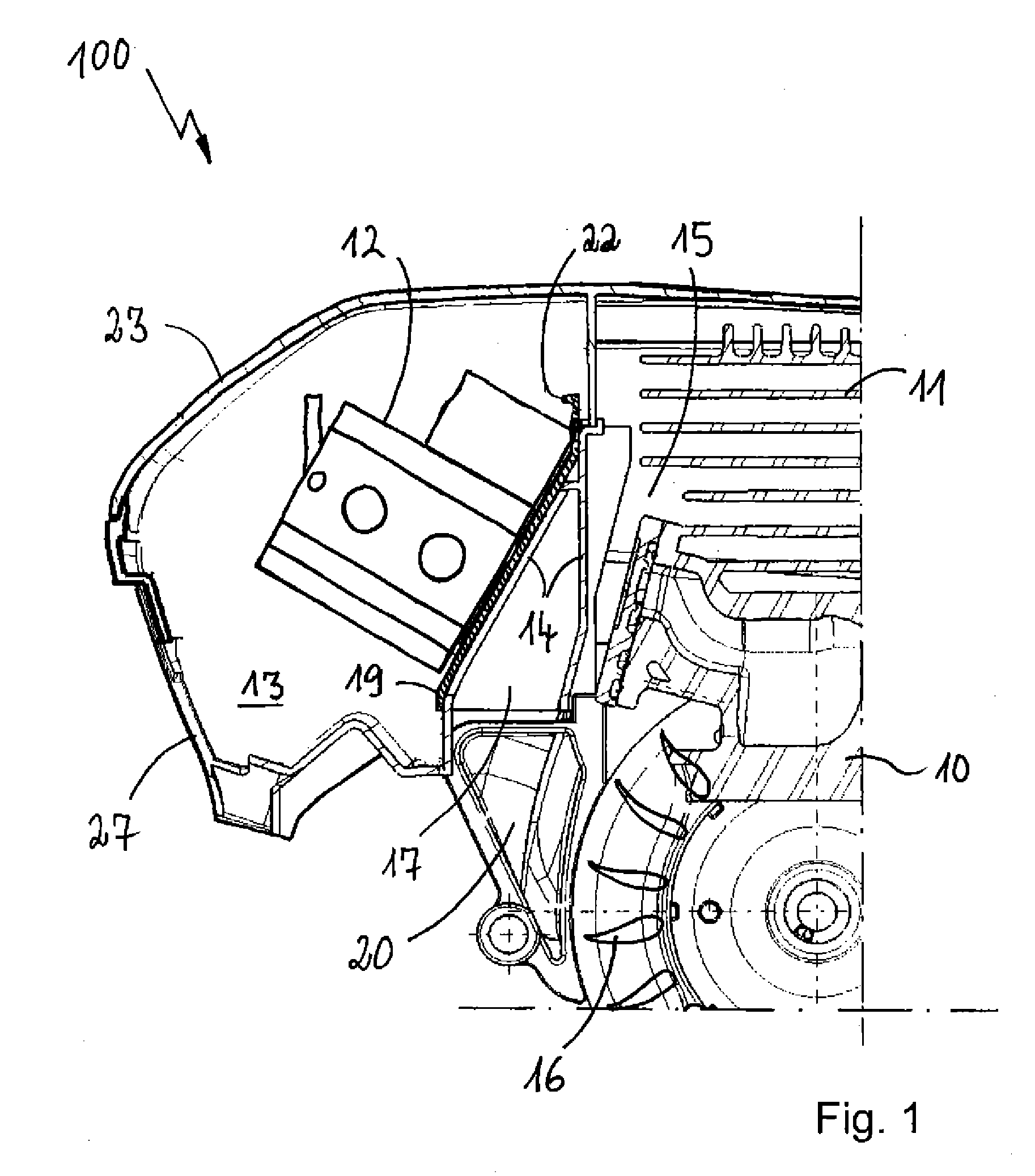
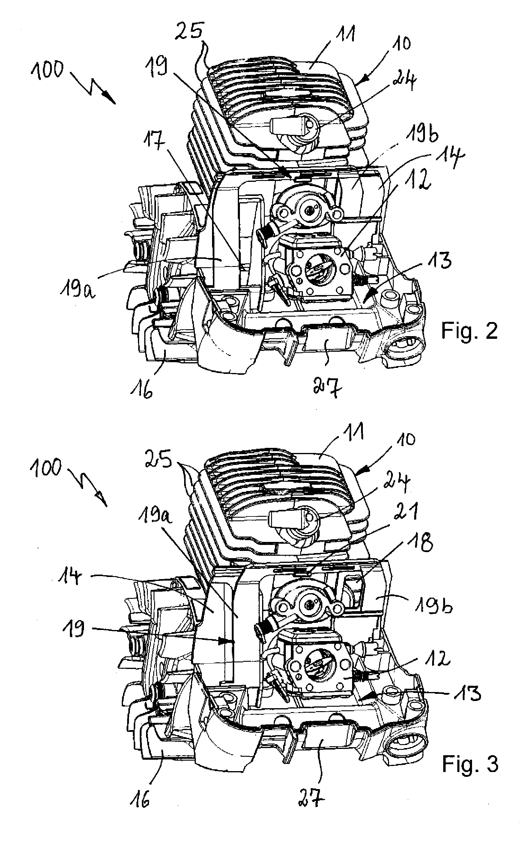
[0020]FIG. 1 shows a section of an exemplary embodiment of a motor-driven implement 100 according to the invention in a transverse cutaway view. The motor-driven implement can be designed as a chain saw, as a hand grinder, as a hand-held circular saw, as a lawn mower, as a lawn trimmer or as another hand-held tool or device for garden and landscape maintenance and comprises an internal combustion engine 10 with a cylinder 11. A carburettor 12 is provided for operation of the internal combustion engine 10 and the internal combustion engine 10 is disposed in an engine compartment 15 and the carburettor 12 is disposed in a carburettor chamber 15. An intermediate wall 14 extends between the carburettor chamber 13 and the engine compartment 15. For operation of the internal combustion engine 10, combustion air taken from the carburettor chamber 13 is taken in through the carburettor 12. In order that air can pass from the engine compartment 15 into the carburettor chamber 13, an engine c...


PUM


Abstract

A motor driven implement having an internal combustion engine having at least one cylinder and at least one carburettor, which is disposed in a carburettor chamber, which is separated by an intermediate wall from an engine compartment, wherein a fan wheel is further provided by which means air from the engine compartment can be introduced through an engine compartment opening in the intermediate wall into the carburettor chamber. A warm air opening is provided in the intermediate wall, through which the air heated over the cylinder can be introduced into the carburettor chamber and wherein an adjusting element is provided which can be brought into a summer position in which the engine compartment opening is open and the warm air opening is closed and which can be brought into a winter position in which the engine compartment opening is closed and the warm air opening is open.

Description

[0001]The present invention relates to a motor-driven implement such as a chain saw, a hand grinder, a hand-held circular saw, a lawn mower, a lawn trimmer or another hand-held tool or device for garden and landscape maintenance, comprising an internal combustion engine having at least one cylinder and at least one carburettor, which is disposed in a carburettor chamber, which is separated by an intermediate wall from an engine compartment, wherein a fan wheel is further provided by which means air from the engine compartment can be introduced through an engine compartment opening in the intermediate wall into the carburettor chamber.PRIOR ART[0002]Known from document DE 10 2009 008 055 A1 is a generic motor-driven implement comprising an internal combustion engine in an engine compartment and comprising a carburettor in a carburettor chamber, where the carburettor chamber and the engine compartment are separated by an intermediate wall. A closure element is provided in an engine co...

Claims


Application Information

Patent Timeline
Patent Type & Authority Applications(United States)
IPC IPC(8): F02M31/14
CPCF02B63/02F02M15/02F02M31/066F02M31/145Y02T10/126F02M35/1017F02M35/1019F02M35/10255F02M35/10268F02M35/10013Y02T10/12
Inventor EWALD, JORG
Owner MAKITA CORP
Why Eureka
Try Eureka