System and method for characterizing a load at the end of a cable

Active Publication Date: 2009-02-05
TEXAS INSTR INC
View PDF5 Cites 29 Cited by
  • Summary
  • Abstract
  • Description
  • Claims
  • Application Information

AI Technical Summary

Benefits of technology

[0008]Following the recharge interval Ra, a second test current, which differs from the first test current, is applied to the communication cable. The second test current may be generated by a second current source, via use of a voltage or current controlled current source, or via any other suitable technique. The voltage on the output port of the PSE produced by the passage of the second test current through the PD, including the load, is applied to the voltage to current converter to generate a discharge current that is used to de-integrate the capacitor Cint from the intermediate voltage. The discharge current is proportional to the output port voltage by the proportionally factor (f). The capacitor Cint is discharged for the discharge interval Da to a final voltage Vf. The durations of the recharge and discharge intervals Ra and Da are equal in length, however, the recharge and discharge currents applied to the capacitor Cint during the recharge and discharge intervals are different. After the time period Da, the voltage Vf on the capacitor Cint is tested to determine if the

Problems solved by technology

This determination can be complicated for a number of reasons.
Moreover, if the load is shunted by a large capacitance, a DC measurement may be distorted since the voltage across the shunt capacitance may not stabilize prior to complet

Method used


Image

  • System and method for characterizing a load at the end of a cable
  • System and method for characterizing a load at the end of a cable
  • System and method for characterizing a load at the end of a cable

Examples


Embodiment Construction

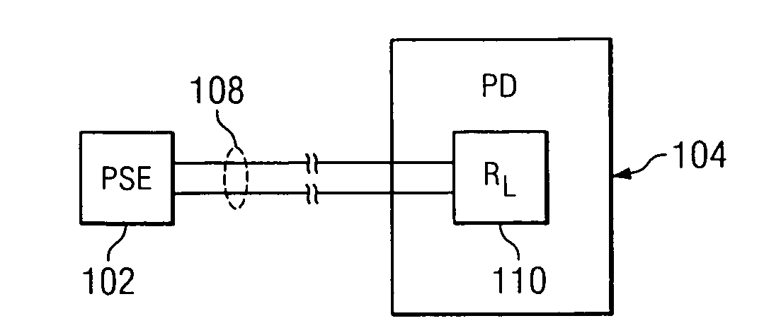
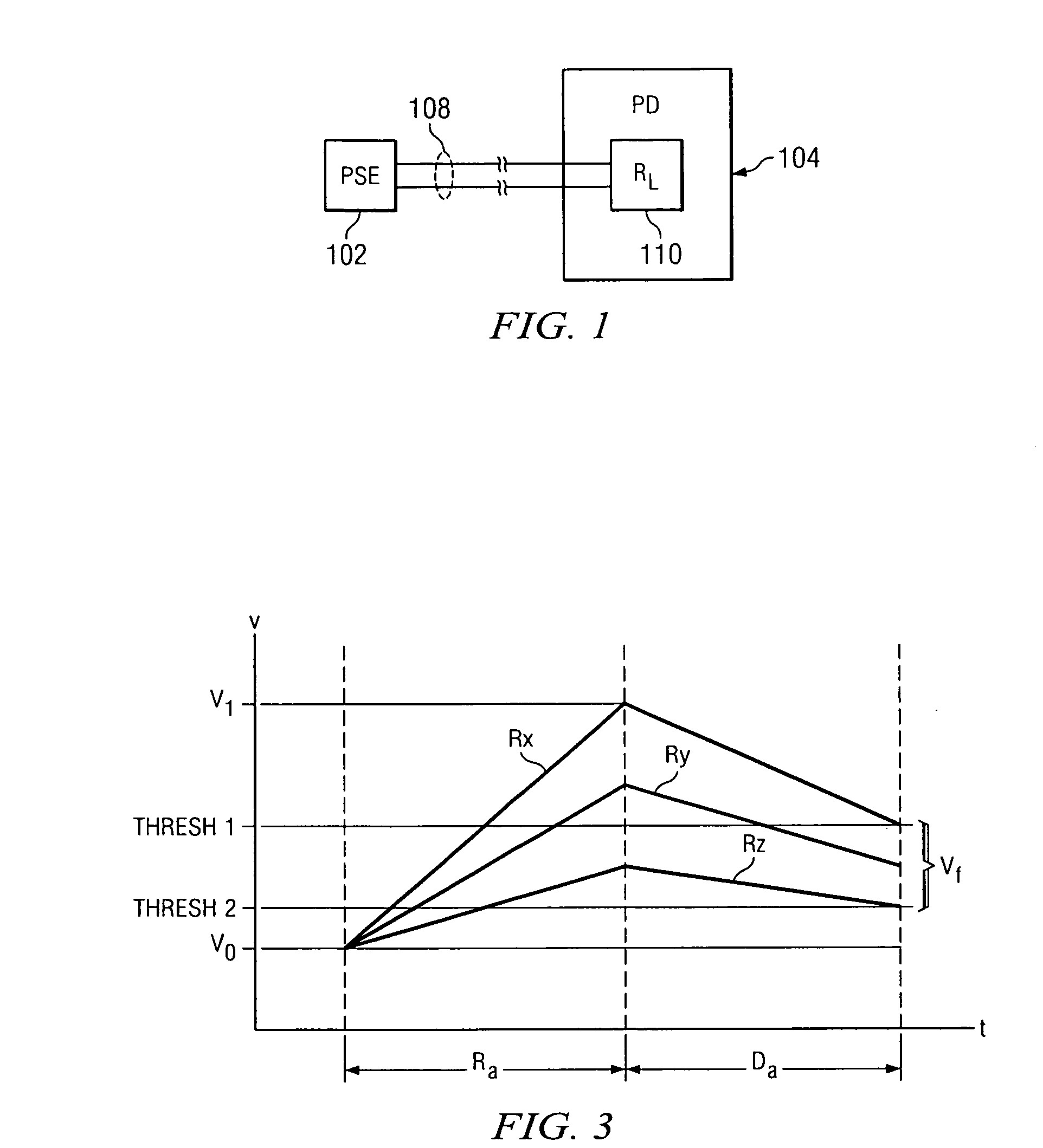
[0025]A system and method in accordance with the present invention are disclosed for determining within a PSE whether a load within a PD that is coupled to the PSE via a communications cable is within a predetermined acceptable range of resistance. A system 100 operative in accordance with the present invention is generally illustrated in FIG. 1. Referring to FIG. 1 the system 100 includes a PSE 102 coupled to a PD 104 via a communication cable 108. The PSE 102 provides power to the PD 104 over the cable 108. Prior to applying power to the cable 108, the PSE 102 performs a test to determine if the resistance of a load RL 110 coupled to the cable 108 (either directly or via series connected diodes) is within an acceptable range of resistances. For example, in accordance with the Power Over Ethernet (PoE) standard IEEE 802.3af dated April 2004, which is incorporated herein by reference, the load RL 110 is deemed to be acceptable if within a range between 17,000 ohms and 29,000 ohms. I...


PUM


Abstract

Apparatus within power sourcing equipment and a method for determining whether a load within a powered device coupled to the power sourcing equipment via a cable is within an acceptable resistance range. If the load is within the acceptable resistance range, a voltage source is coupled to the load. In one embodiment one recharge interval is employed during which a capacitor is charged based, at least in part, on the voltage drop across the load and one discharge interval is employed during which a capacitor is discharged based, at least in part, on the voltage drop across the load. In a second embodiment, first and second recharge and discharge intervals are employed and prior to initiation of the recharge and discharge intervals, settling time periods are provided.

Description

CROSS REFERENCE TO RELATED APPLICATIONS[0001]Not ApplicableSTATEMENT REGARDING FEDERALLY SPONSORED RESEARCH OR DEVELOPMENT[0002]Not ApplicableBACKGROUND OF THE INVENTION[0003]The present invention relates to techniques for delivering power over a data communications cable, such as a category 5 cable or equivalent, and more particularly, to a system and method for characterizing a load at the end of a communication cable prior to delivering power to the load.[0004]In Power over Ethernet (PoE) systems, it is desirable to determine the resistance of a load within a powered device (PD) that is powered by power sourcing equipment (PSE) to ascertain whether the PSE should apply power to the load. This determination can be complicated for a number of reasons. First, a communications cable coupling the PSE to the PD may be coupled directly to the load or alternatively, may be coupled to the load via a diode rectifier or a diode bridge. Moreover, if the load is shunted by a large capacitance...

Claims


Application Information

Patent Timeline
IPC IPC(8): G01R27/02
CPCH04L12/10
Inventor PICARD, JEANWANG, LINMILLER, WILBURN M.NEIDORFF, ROBERT A.SERRANO, GUILLERMO J.
Owner TEXAS INSTR INC
Why Eureka
Try Eureka