Three-dimensional virtual input and simulation apparatus
- Summary
- Abstract
- Description
- Claims
- Application Information
AI Technical Summary
Problems solved by technology
Method used
Image
Examples
second embodiment
[0292]In addition, according to the unique characteristics, the composition of the unique characteristics of the plurality of point light sources can be a combination of the uniqueness of intensity, geometric size and wavelength. In other words, such a combination is an application integrated by the first and For instance, as to three sets of point light sources, each set of point light sources is composed of a plurality of point light sources; and as to the composition of the unique characteristics, each set has the unique wavelength characteristics (such R, G, B wavelength), while each point light source in each set may have the unique intensity characteristics or unique geometric size characteristics. Principle and effect of such combination has been disclosed in the above description and it is no necessary to repeat it again.
[0293]With reference to FIG. 15(a) for a schematic view of the third preferred embodiment, as for the unique characteristics of the point light sources, th...
first embodiment
[0299]With reference to FIG. 15(c) for a schematic view of a 1D optical positioning devices with a visual axis tracking function, being different from the composition in the first embodiment, the 1D optical positioning devices 331 comprises one more RF transmitter 332 for emitting or receiving the coded RF synchronous signal 320 which is generated by the positioning calculation control microprocessor 345. The encoding signal in the coded RF synchronous signal 320 can be composed of a group of binary codes, a square wave with specific time duration, or a specific number of pulses. If the 1D optical positioning devices 331 is selected as a master device, then the RF transmitter 332 is used to emit the coded RF synchronous signal 320. If the 1D optical positioning devices 331 is selected as a client device, then the RF transmitter 332 is used to receive the coded RF synchronous signal 320 and also produces a synchronization scan signal SYNC to synchronously drive all linear optical sen...
sixth embodiment
[0313]As for the unique characteristics of the point light sources, the sixth embodiment adopts another improved time modulation method, namely the aforementioned the improved Stephenson's method, and has a same system structure as the one disclosed in the first preferred embodiment. Only the difference is described as follow.
[0314]The device 600 in the present embodiment mainly comprises a module device of multiple point light sources 611, a plurality of 1D optical positioning devices with a visual axis tracking function 630 and a control analysis procedure 690.
[0315]The difference is described as follow:
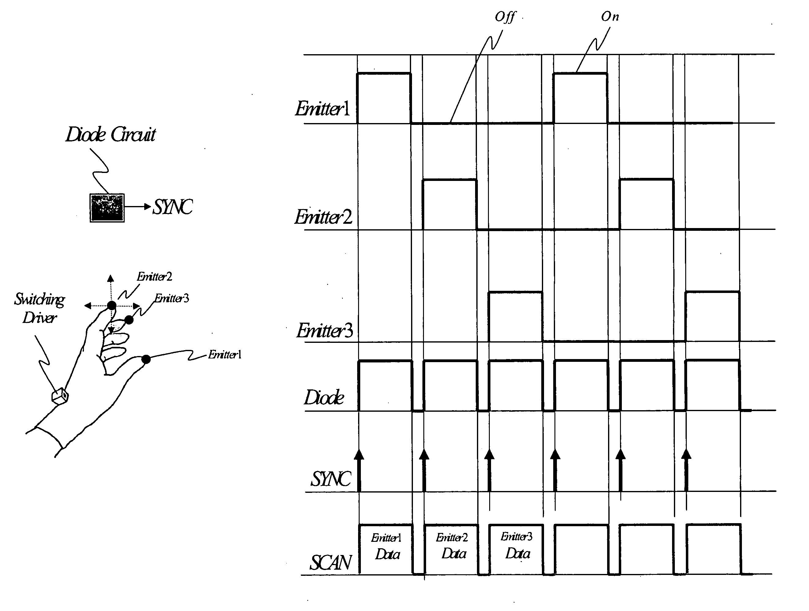
[0316](1) One more switch 614 is installed in the module device of multiple point light sources 611, and is used to continuously and alternately light the point light sources 612 for emitting a point-like scattering light source 613 at a constant period.
[0317](2) An optical receiver 632 installed in each 1D optical positioning devices 631 is used to receive the light sources 613 em...
PUM
 Abstract
Description
Claims
Application Information
 - R&D
- Intellectual Property
- Life Sciences
- Materials
- Tech Scout
- Unparalleled Data Quality
- Higher Quality Content
- 60% Fewer Hallucinations
Browse by: Latest US Patents, China's latest patents, Technical Efficacy Thesaurus, Application Domain, Technology Topic, Popular Technical Reports.
© 2025 PatSnap. All rights reserved.Legal|Privacy policy|Modern Slavery Act Transparency Statement|Sitemap|About US| Contact US: help@patsnap.com


