
Measuring method and arrangement to determine the play of an ink jet cartridge pivot unit

a technology of inkjet printing system and pivot unit, which is applied in the direction of printing, power drive mechanism, printing, etc., can solve the problems of machine malfunction, and achieve the effect of increasing the precision of the pivoting into the printing position and the time duration of the pivoting

Inactive Publication Date: 2009-02-05
FRANCOTYP POSTALIA
View PDF8 Cites 5 Cited by
  • Summary
  • Abstract
  • Description
  • Claims
  • Application Information

AI Technical Summary

Benefits of technology

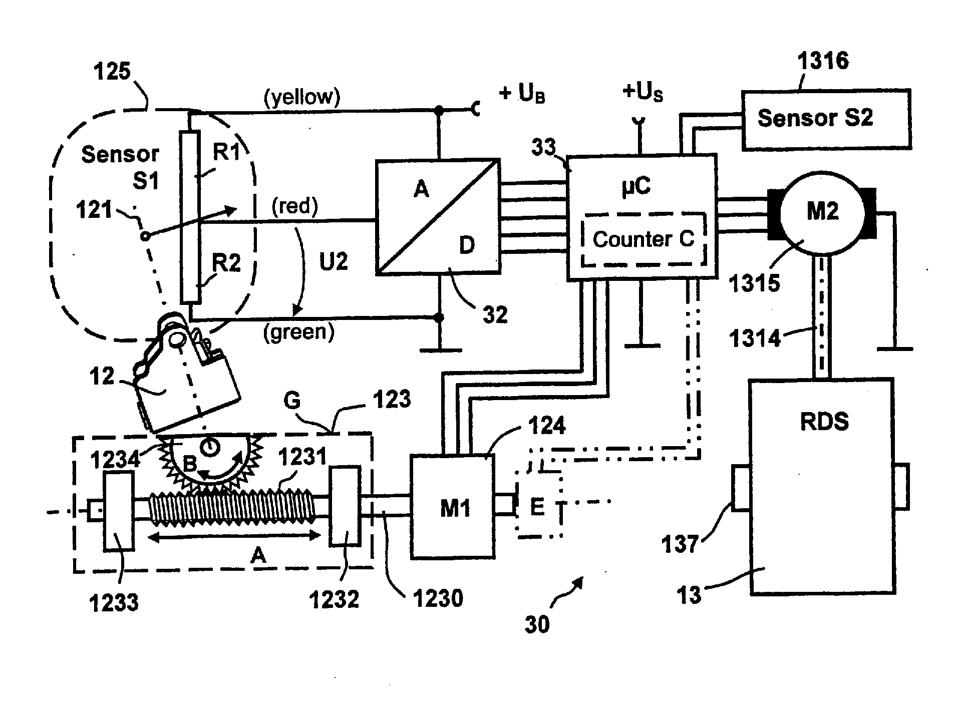
[0009]An object of the present invention is to provide a measuring arrangement to determine the play of a cartridge pivot unit and a corresponding measurement method, wherein testing evaluation) of the play is made possible in a simple manner and without opening the machine.
[0013]The invention has the advantage that the time duration of the pivoting of the cartridge pivot unit with the at least one inkjet print head from the exchange position into the sealing position to stop at the RDS and back again into the exchange position is short relative to a pivoting of the cartridge pivot unit onto the fixed stop in the printing position. The cartridge pivot unit is held by its inherent weight in the sealing position while the drive direction of the train is reversed. Until the cartridge pivot unit moves and is pivoted back into the exchange position, its play can be determined very precisely in an advantageous manner. The precision in the pivoting into the printing position is increased by taking this play into consideration, such that a fixed stop in the printing position at the frame of the inkjet printing system, that is provided to prevent an overrun of the printing position, could even be omitted.

Problems solved by technology

The cartridge pivot unit can have too much play even given a correctly adjusted rotation angle transmitter, which can lead to a malfunction of the machine.

Method used


Image

  • Measuring method and arrangement to determine the play of an ink jet cartridge pivot unit
  • Measuring method and arrangement to determine the play of an ink jet cartridge pivot unit
  • Measuring method and arrangement to determine the play of an ink jet cartridge pivot unit

Examples


Embodiment Construction

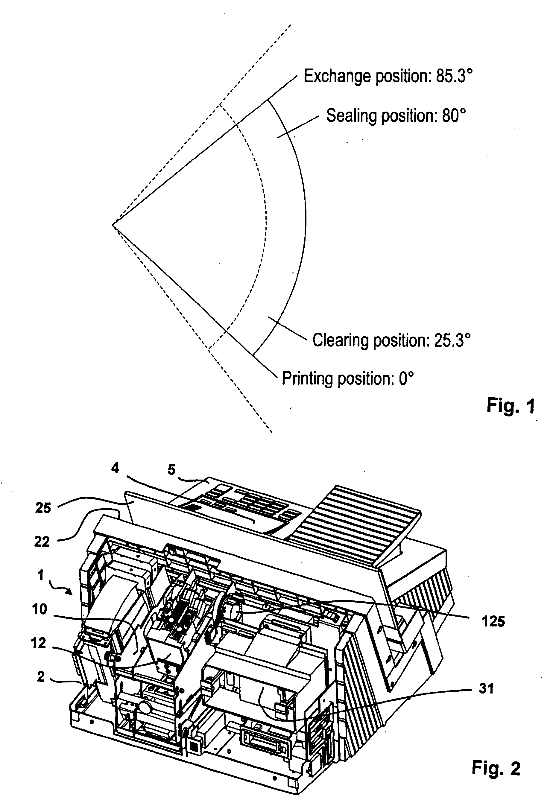
[0021]FIG. 1 shows a representation of the positions of the rotation angle of a cartridge pivot unit. At least one inkjet print head of a cartridge can be moved into the desired position with the aid of the cartridge pivot unit. The cartridge pivot unit can occupy the position shown in FIG. 1 and has a pivot range of 85.3°. A printing position corresponds to an angle of zero degrees. A clearing position near the printing position corresponds to an angle of 25.3°, a sealing position corresponds to an angle of 80° and an exchange position corresponds to an angle of 85.3°. The cartridge pivot unit is moved by a worm drive with a prime mover that is not shown, advantageously with the use of a step motor. A reserve angle range (margin) lies at both boundaries of the aforementioned angle range of 85.3°. If a known rotation angle transmitter that has an electrical usable angle of 95° is used to determine the play of the cartridge pivot unit, the approximately equal angle reserves amount to...


PUM


Abstract

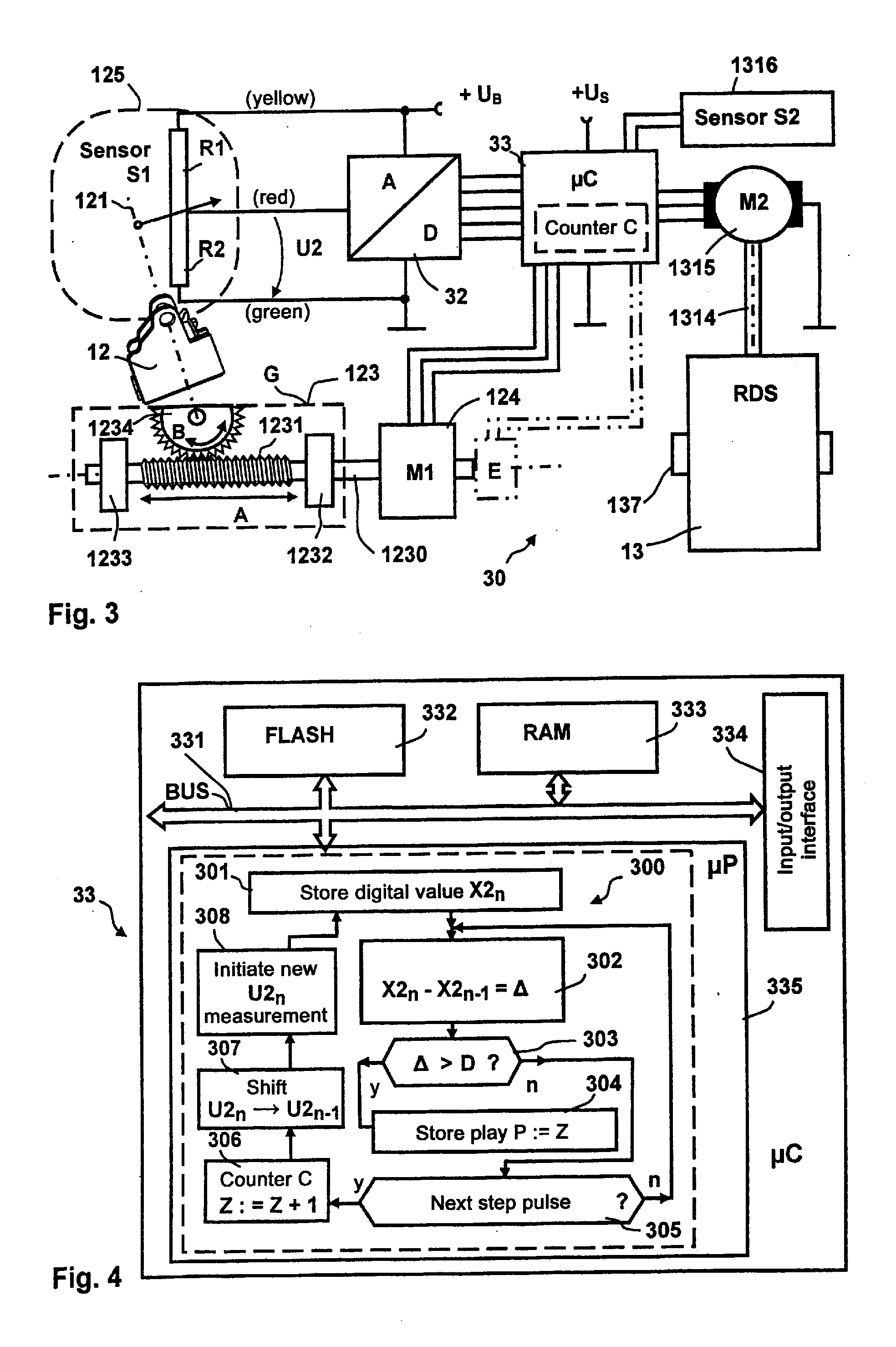
A measuring arrangement and measurement method determine the play of a cartridge pivot unit of an inkjet printing system that has at least one stop for the cartridge pivot unit. The cartridge pivot unit is driven by a first motor via a gear train and is equipped with a first movement sensor to establish a movement of the cartridge pivot unit upon leaving the stop. The cartridge pivot unit moves only when the play of the gear train is overcome. The stop for the cartridge pivot unit is formed by a mobile cleaning and sealing station. A counter is provided to count pulses, the count being representative of the play of the gear train of the cartridge pivot unit counting begins with leaving the mobile stop and continues until the movement of the cartridge pivot unit upon leaving the stop again ensues in conformity with the actuation by the first motor.

Description

BACKGROUND OF THE INVENTION[0001]1. Field of the Invention[0002]The invention concerns a measuring arrangement and a measurement method to determine the play of a cartridge pivot unit of an inkjet printing system. The method serves to detect and compensate for age-dependent variations of the play and to assess whether the required precision in the pivoting of the cartridge pivot unit into the printing position can still be maintained. The invention is used in printing devices with relative movement between an inkjet print head and the print item, in particular in franking and / or addressing machines and in other mail processing apparatuses.[0003]2. Description of the Prior Art[0004]Pivot movements of a print head are known from German Utility Model DE 200 12 946 U1.[0005]An acceptance unit is known from DE 10062012 A1 for at least one inkjet print head that is arranged so that it can move in rotation around a rotation axis that lies parallel to the transport direction of mail pieces ...

Claims


Application Information

Patent Timeline
Patent Type & Authority Applications(United States)
IPC IPC(8): B41J29/393
CPCB41J25/308B41J2/16588
Inventor EHRESMANN, RAINERMUELLER, RALFMUHL, WOLFGANGROTH, SABINE
Owner FRANCOTYP POSTALIA
Learn More