Inspection device, inspection method, method of manufacturing color filter, and computer-readable storage medium containing inspection device control program

a color filter and inspection method technology, applied in the direction of identification means, instruments, optical apparatus testing, etc., can solve the problems of linear irregularities, serious affecting the quality of liquid crystal display, and the use of inkjet technology in color filter fabrication

Inactive Publication Date: 2009-02-05
SHARP KK
View PDF12 Cites 5 Cited by
  • Summary
  • Abstract
  • Description
  • Claims
  • Application Information

AI Technical Summary

Benefits of technology

[0032]Under these circumstances, if linear irregularities occur due to a less-than-normal thickness of the surface mounds on the inspection object, the linear irregularities are detectable from no matter which direction light is projected. In contrast, if non-uniform deformation irregularities occur, the linear irregularities may not be detected depending on the direction of projected light.
[0033]From the extracted linear irregularities occurring at a specific cycle, the arrangement further extracts those detected in both the first and second images, that is, the linear irregularities detect...

Problems solved by technology

The use of inkjet technology in color filter fabrication however has a disadvantage: linear irregularities could develop at a specific cycle due to a cause in the manufacturing process of the color filter.
They are visible (by light transmitting through the color filter) and could seriously affect the quality of the liquid crystal display.
Color filters with linear irregularities are of poor quality as mentioned earlier and need to be detected in the manufacturing stage to reject them.
Trouble is that the linear irregularities on a color filter develop due to deviations in thickness of the color filter on the order of 10 to 100 nm: it is difficult to detect the linear irregularities by a thickness measuring method that exploits light interference or transmitted light.
The technology of patent document 1 is not suitable for detection of linear irregularities which occur at predetermined specific cycles because a p...

Method used


Image

  • Inspection device, inspection method, method of manufacturing color filter, and computer-readable storage medium containing inspection device control program
  • Inspection device, inspection method, method of manufacturing color filter, and computer-readable storage medium containing inspection device control program
  • Inspection device, inspection method, method of manufacturing color filter, and computer-readable storage medium containing inspection device control program

Examples


embodiment 1

Inspection System Structure

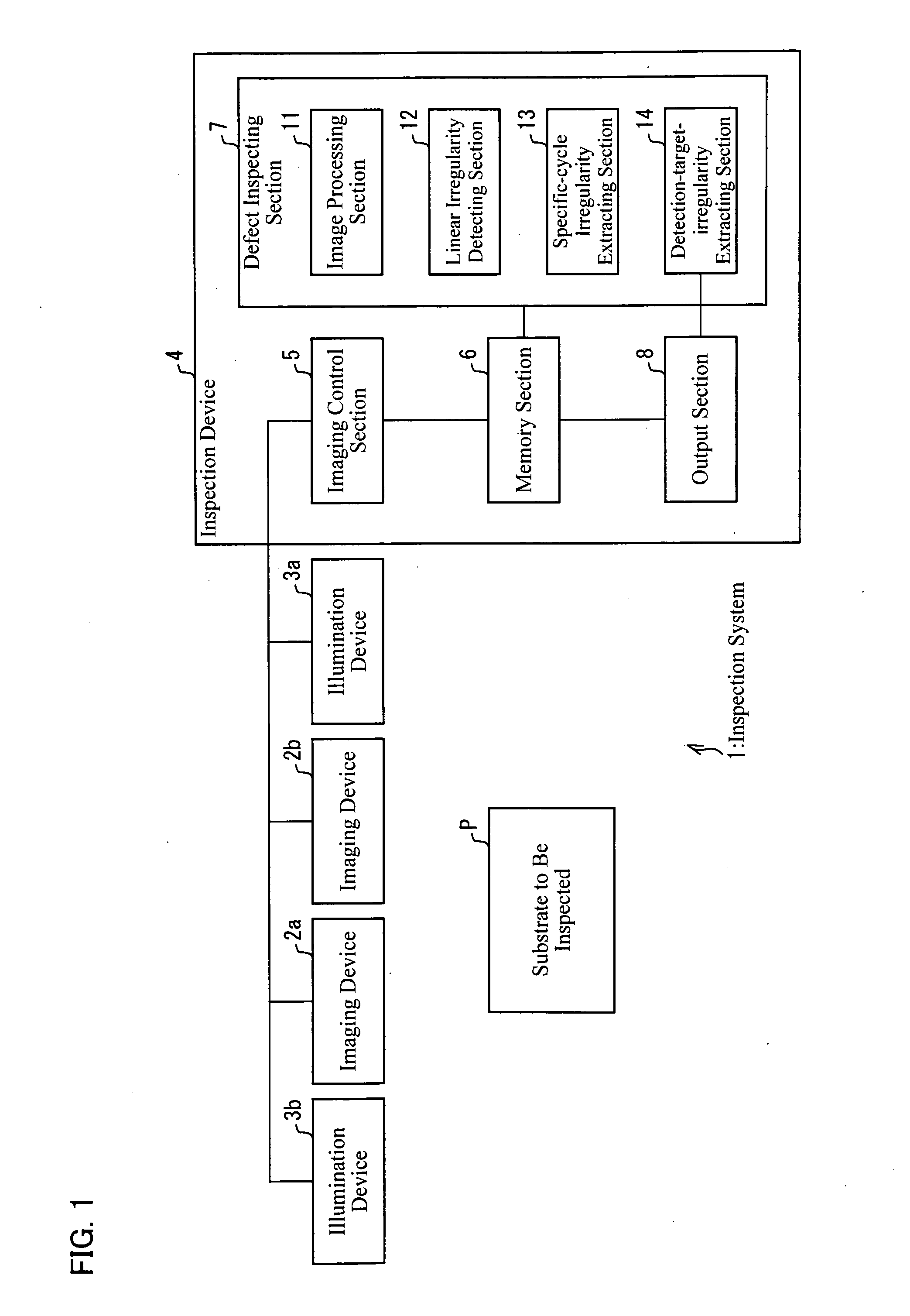
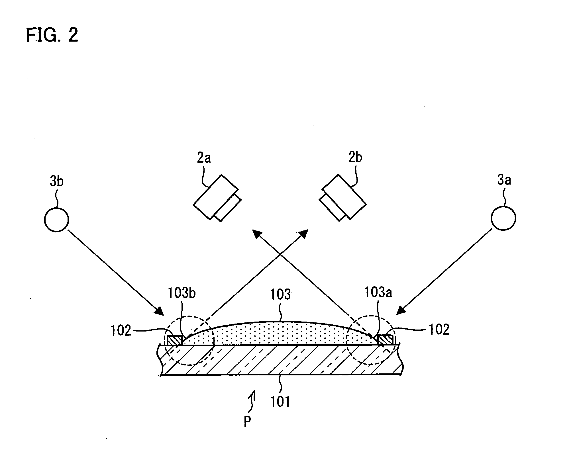
[0046]The following will describe an embodiment of the present invention in reference to FIGS. 1 to 7. First, an inspection system 1 of the present embodiment will be schematically described in reference to FIG. 1. FIG. 1 is a schematic block diagram of the inspection system 1. As illustrated, the inspection system 1 inspects a substrate P and is composed primarily of an imaging device 2a, an imaging device 2b, an illumination device 3a, an illumination device 3b, and an inspection device 4.

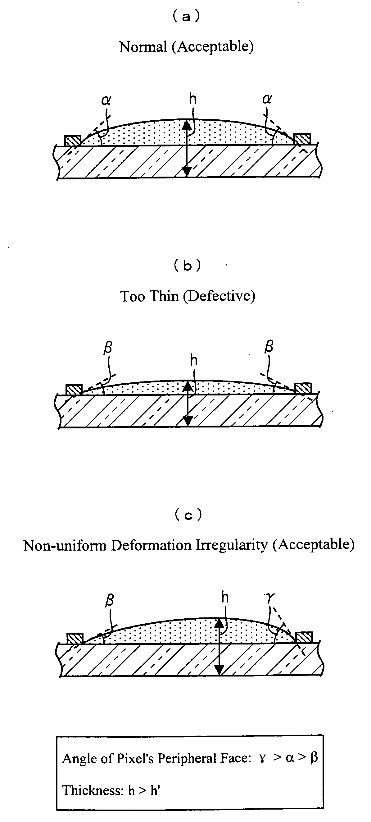
[0047]Here, the substrate P to be inspected by the inspection system 1 is assumed to be a color filter substrate. A “color filter,” throughout the following description, refers to a filter enabling a color display on a display device by transmitting particular wavelengths of light. The color filter is assumed to be formed by ejecting liquid substances by inkjet technology onto a glass substrate on which a black matrix has been formed. In this context, a glass substrate ...

embodiment 2

[0098]The preceding embodiment gave an example of detecting linear irregularities from a single image L and another single image R. The present embodiment will discuss an example in which, the images L and R are divided into corresponding regions so as to detect linear irregularities in each region. The division of the images L and R into regions improves precision in the detection of linear irregularities. Here, for convenience, members of the present embodiment that have the same arrangement and function as members of the preceding embodiment, and that are mentioned in that embodiment are indicated by the same reference numerals and description thereof is omitted.

[0099]An inspection system 1 of the present embodiment has the same configuration as in the preceding embodiment, except that the inspection device 4 has an image dividing section (image dividing means). Linear irregularities detection is performed by the same process as the one shown in FIG. 3. Accordingly, the following...


PUM


Abstract

An inspection device of the present invention includes: a linear irregularity detecting section for detecting linear irregularities individually in an image L of dots on a substrate being inspected by projecting light from a first direction and in an image R of the dots by projecting light from a second direction, which differs from the first direction; a specific-cycle irregularity extracting section for extracting linear irregularities detected at predetermined intervals T in the individual mages L and R, the intervals being taken vertical to the linear irregularities on the substrate; and a detection-target-irregularity extracting section for extracting a linear irregularity detected in both the images L and R as a detection-target linear irregularity. The device therefore is capable of detecting only linear irregularities of a specific cycle which are caused by the presence of dots having irregular thickness when compared to a dot with normal thickness.

Description

[0001]This nonprovisional application claims priority under 35 U.S.C. §119(a) on Patent Application No. 2007-199979 filed in Japan on Jul. 31, 2007, the entire contents of which are hereby incorporated by reference.FIELD OF THE INVENTION[0002]The present invention relates to, among others, inspection devices that detect linear irregularities which develop at a specific cycle (or at a specific period) on an inspection object having surface mounds, by inspecting images captured of the peripheries of the surface mounds.BACKGROUND OF THE INVENTION[0003]Liquid crystal displays have become bigger in size over recent years, and demand for such displays is ever growing. However, price needs to be cut to see more widespread use of liquid crystal displays. There is an increasing demand to cut down the cost of, especially, the color filter, which is a relatively expensive component in the liquid crystal display.[0004]A recent notable trend is use of inkjet technology in the fabrication of colo...

Claims


Application Information

Patent Timeline
IPC IPC(8): G06K9/00G03F1/00G01B11/24G01M11/00G01N21/88G02B5/20G02F1/13G02F1/1335G09F9/00
CPCG01B11/245G01N21/8851G01N21/95G02B5/223G01N2021/9511G01N2021/9513G01N2021/8887
Inventor IDEN, TAMON
Owner SHARP KK
Why Eureka
Try Eureka