Drying apparatus

a technology of drying apparatus and motor, which is applied in the direction of lighting and heating apparatus, air heaters, applications, etc., can solve the problems of unacceptably high noise emitted by the motor suitable for generating an airflow of sufficiently high momentum adequate to dry the user's hands, and achieve the effect of reducing noise emitted by the apparatus, reducing noise emitted by the motor, and efficient drying of the user's hands

Inactive Publication Date: 2009-02-05
DYSON TECH LTD
View PDF100 Cites 53 Cited by
  • Summary
  • Abstract
  • Description
  • Claims
  • Application Information

AI Technical Summary

Benefits of technology

[0005]It is an object of the invention to provide drying apparatus in which an airflow of sufficient momentum efficiently to dry the user's hands is produced and in which the noise emitted by the motor is further improved in comparison to prior art and known devices. It is a further object of the present invention to provide drying apparatus in which the noise emitted by the apparatus is comparatively low.
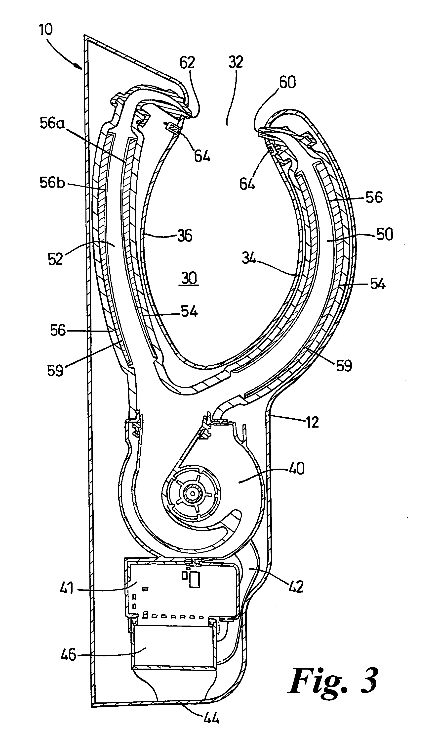
[0007]The provision of a sound-absorbing material on the outside of the perforated wall reduces the volume of aero-acoustic noise emitted by the apparatus which, in the case of a hand dryer, renders the hand dryer more comfortable to use.
[0008]Preferably, the perforations in the wall are elongate and extend generally in the direction of the airflow along the air duct. More preferably, the length of each perforation is significantly larger than the width thereof. Such an arrangement provides the wall with a significant area of perforation without significantly affecting the structural strength of the wall.

Problems solved by technology

However, in practice it is very difficult to achieve an evenly distributed airflow of sufficiently high momentum to dry the user's hands efficiently in an acceptably short length of time.
Furthermore, the amount of noise emitted by a motor suitable for generating an airflow of sufficiently high momentum adequately to dry the user's hands can be unacceptably high.

Method used


Image

  • Drying apparatus
  • Drying apparatus
  • Drying apparatus

Examples


Embodiment Construction

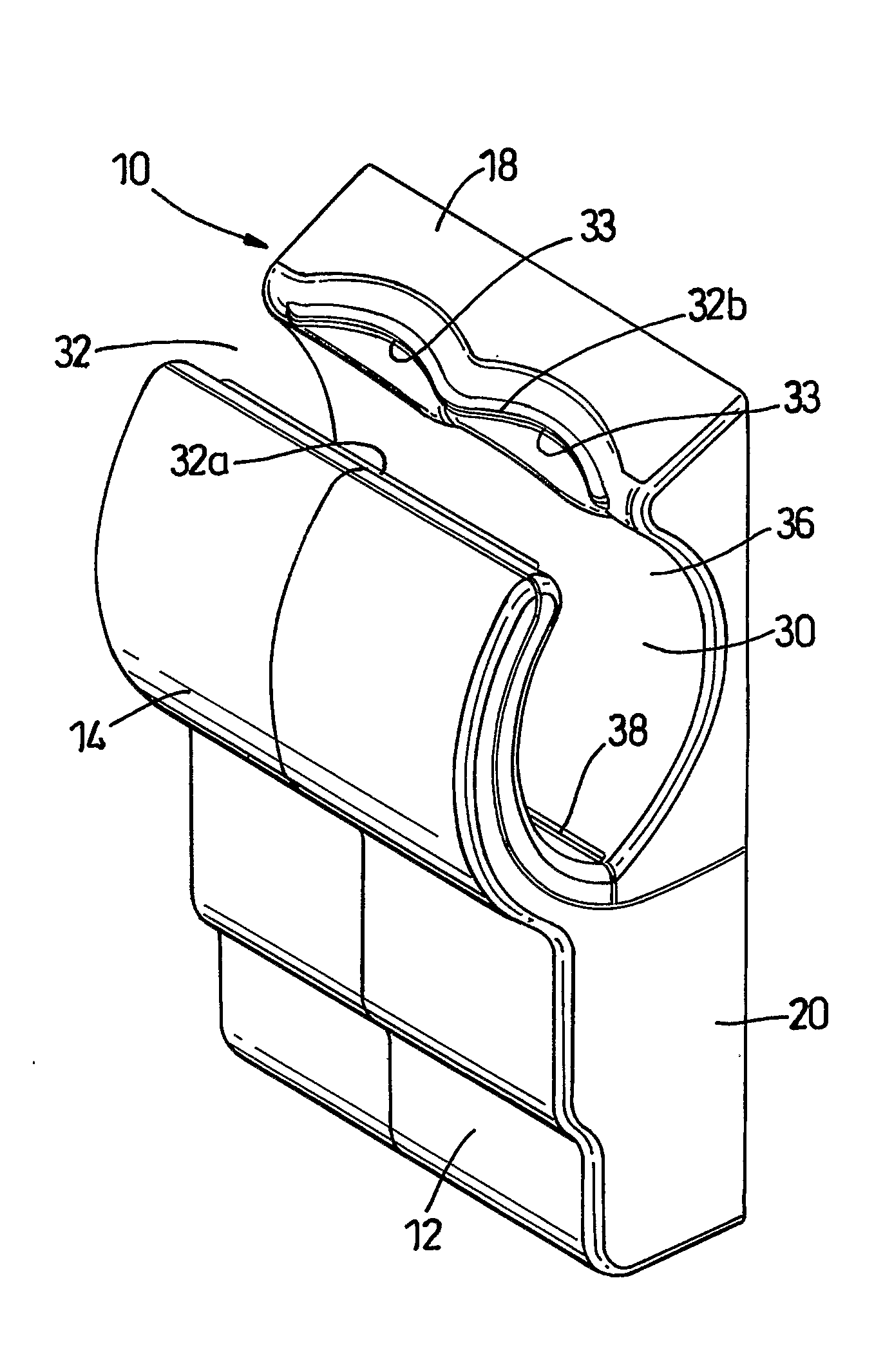
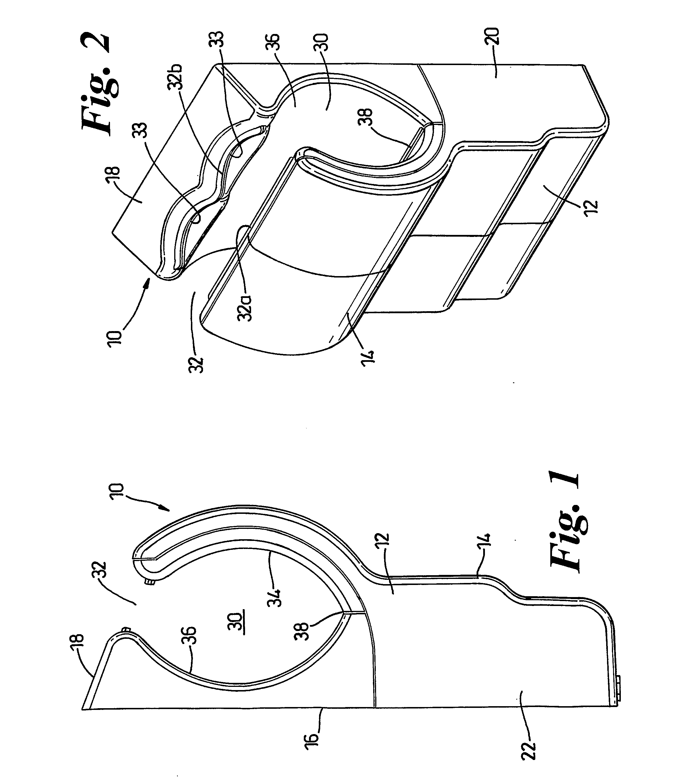
[0021]Referring firstly to FIGS. 1 and 2, the hand dryer 10 shown in the drawings comprises an outer casing 12 having a front wall 14, a rear wall 16, an upper face 18 and side walls 20, 22. The rear wall 16 can incorporate fixing devices (not shown) for securing the hand dryer 10 to a wall or other structure prior to use. An electrical connection (not shown) is also provided on the rear wall or elsewhere on the casing 12. A cavity 30 is formed in the upper part of the casing 12 as can be seen from FIGS. 1 and 2. The cavity 30 is open at its upper end and delimited thereat by the top of the front wall 14 and the front of the upper face 18. The space between the top of the front wall 14 and the front of the upper face 18 forms a cavity entrance 32 which is sufficiently wide to allow a user's hands to be introduced to the cavity 30 through the cavity entrance 32. The cavity 30 is also open to the sides of the hand dryer 10 by appropriate shaping of the side walls 20, 22.

[0022]The cavi...


PUM


Abstract

A drying apparatus includes a casing and a cavity formed in the casing for receiving an object to be dried. A fan is located in the casing so as to be capable of creating an airflow, and a motor is provided in the casing for driving the fan. Ducting is provided for carrying the airflow from the fan to at least one opening arranged to emit the airflow into the cavity (12). The ducting includes at least one air duct having a wall in which perforations are provided, and a layer of sound-absorbing material is located on the external surface of the wall so as to cover the perforations. The invention is particularly suitable for use in hand dryers.

Description

REFERENCE TO RELATED APPLICATIONS[0001]This application is a national stage application under 35 USC 371 of International Application No. PCT / GB2007 / 000089, filed Jan. 12, 2007, which claims the priority of United Kingdom Application No. 0600534.2, filed Jan. 12, 2006, the contents of both of which prior applications are incorporated herein by reference.FIELD OF THE INVENTION[0002]The invention relates to drying apparatus which makes use of a narrow jet of high velocity, high pressure air to dry an object, including part of the human body. Particularly, but not exclusively, the invention relates to a hand dryer in which the air jet is emitted through a slot-like opening in the casing of the hand dryer.BACKGROUND OF THE INVENTION[0003]The use of air jets to dry hands is well known. Examples of hand dryers which emit at least one air jet through a slot-like opening are shown in GB 2249026A, JP 2002-034835A and JP 2002306370A. However, in practice it is very difficult to achieve an eve...

Claims


Application Information

Patent Timeline
Patent Type & Authority Applications(United States)
IPC IPC(8): A47K10/48F26B21/04
CPCA47K10/48B05B1/044
Inventor CAINE, JOSEPH ZACARYSIMMONDS, KEVIN JOHNFRENCH, TIMOTHY ALEXANDER
Owner DYSON TECH LTD
Why Eureka
Try Eureka