Image Forming Device

a technology of forming device and toner, which is applied in the direction of electrographic process apparatus, instruments, optics, etc., can solve the problems of difficult structure, large differences in the correspondence relationship between the amount of toner usage and the actual amount of toner consumption, and achieve the effect of reducing the amount of error

Active Publication Date: 2009-02-05
SEIKO EPSON CORP
View PDF5 Cites 7 Cited by
  • Summary
  • Abstract
  • Description
  • Claims
  • Application Information

AI Technical Summary

Benefits of technology

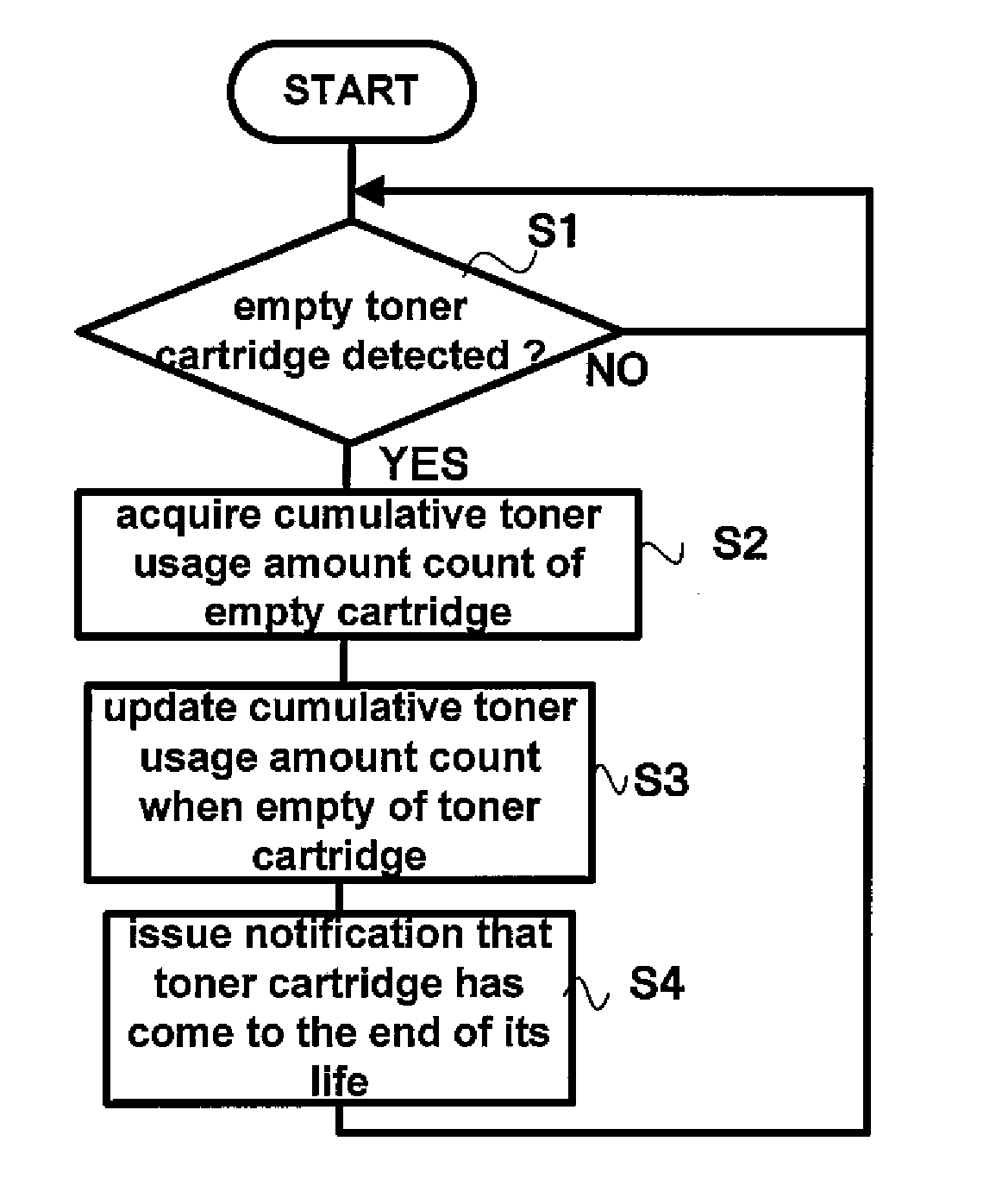
[0032]According to this refill determination method, since it is arranged to make the determination as to whether or not the subject cartridge is a refilled product by using the amount of change of the image forming material usage amount count from the time point that the predetermined state is detected, accordingly, with regard to the threshold value which is used for comparison, it is possible to reduce the amount of error which must be included in this threshold value, since it is sufficient to give consideration to error of the image forming material usage amount count corresponding to the state of usage from the time point at which the predetermined state is detected. Accordingly, if this image forming material cartridge is a refilled product, it becomes possible to determine that it is a refilled product at an earlier stage.

Problems solved by technology

However, with the invention described in JP-A-2002-331686, there is the problem that it is necessary to provide a structure for detecting the actual remaining amount of ink.
For example, it is extremely difficult to detect the remaining amount of toner in a toner cartridge, so that it is extremely difficult to provide a structure for doing so.
On the other hand, if it is arranged to keep a running total of a toner usage amount count from the start of use, and to determine that the cartridge is a refilled product if this has exceeded a predetermined threshold value, then the following type of problem arises.
Accordingly there is a fear that the correspondence relationship between the toner usage amount count and the actual amount of toner consumption will be very much different, depending upon the circumstances of use by the user.
In order to prevent the occurrence of this type of mistaken decision, it is necessary to set the threshold value to be a large value, but, even if this is done it is difficult perfectly to prevent mistaken decisions, unless the threshold value is extremely large.
On the other hand, if the threshold value is set to be a larger value, then it becomes possible to suppress the occurrence of mistaken decisions to a comparatively large extent, but, since a considerable time period is required until the toner usage amount count arrives at the threshold value, accordingly, even if the subject cartridge is a refilled product, this considerable time period will elapse until it is determined that it is a refilled product, so that there is a fear that the message urging the user to take care will be undesirably delayed.

Method used


Image

  • Image Forming Device
  • Image Forming Device
  • Image Forming Device

Examples


Embodiment Construction

[0038]Embodiments of the invention will now be explained with reference to the drawings. It should be understood that the embodiments explained below are not limitative of the invention as defined by the scope of the Claims; and, moreover, a combination of all of the features explained in the embodiments is not essential to the means for solution of the invention.

[0039]First a laser printer will be explained, as one example of an image forming device according to an embodiment of the invention.

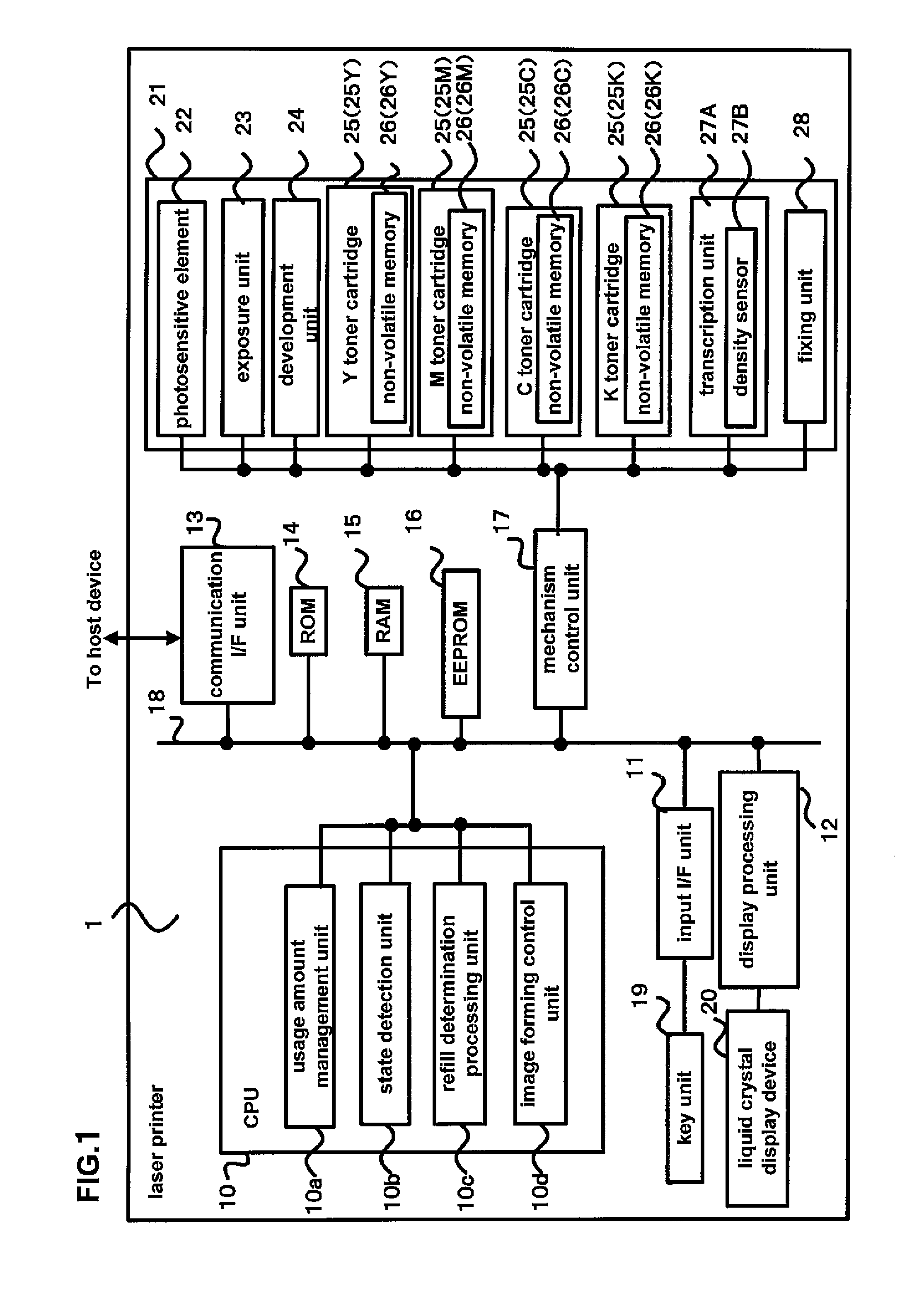
[0040]FIG. 1 is a functional structural diagram of a laser printer according to an embodiment of the invention.

[0041]In the laser printer 1, a CPU (Central Processing Unit) 10, an input interface unit (input I / F unit) 11, a display processing unit 12, a communication interface unit (communication I / F unit) 13, a ROM (Read Only Memory) 14, a RAM (Random Access Memory) 15, an EEPROM (Electrically Erasable Programmable Read-Only Memory) 16, and a mechanism control unit 17 are connected together v...


PUM


Abstract

An image forming device to which can be installed an image forming material cartridge which contains an image forming material, and which has a non-volatile memory from which data can be read and to which data can be written, includes a counter which approximately counts the image forming material usage amount of the image forming material cartridge, and generates an image forming material usage amount count; a state detector which detects a predetermined state in which it is inferred that the amount of the image forming material in the image forming material cartridge is low; a storage unit which stores amount of change information which specifies the amount of change of the image forming material usage amount count from the time point that the predetermined state was detected until the present in the non-volatile memory of the image forming material cartridge; and a determination unit which determines whether or not the image forming material cartridge is a refilled product, based upon the amount of change of the image forming material usage amount count and upon a first threshold value.

Description

CROSS-REFERENCE TO PRIOR APPLICATION[0001]This application relates to and claims the benefit of priority from Japanese Patent Application number 2007-203548, filed on Aug. 3, 2007 the entire disclosure of which is incorporated herein by reference.BACKGROUND[0002]1. Technical Field[0003]The present invention relates to an image forming device in which can be installed an image forming material cartridge which contains an image forming material such as toner, ink, or the like, and which has a non-volatile memory which can be written and read; and, in particular, relates to a technique for determining upon refilling such an image forming material cartridge with image forming material.[0004]2. Related Art[0005]In the past, it has been possible to install a toner cartridge in which toner for forming images is contained into an image forming device which performs image forming such as printing or the like. And, when the toner which was contained in the toner cartridge has been used up, it...

Claims


Application Information

Patent Timeline
Patent Type & Authority Applications(United States)
IPC IPC(8): G03G15/08
CPCG03G21/1889
Inventor MOCHIZUKI, TAKAFUMI
Owner SEIKO EPSON CORP
Why Eureka
Try Eureka