Bookbinding Method, and Bookbinding Unit and Image-Forming System Equipped with the Same

a book binding and image-forming technology, applied in the field of book binding methods and book binding units and image-forming systems equipped with the same, can solve the problems of weak adhesives, defective binding of booklets, and bending of the spine cover

Active Publication Date: 2009-02-05
NISCA KK
View PDF7 Cites 16 Cited by
  • Summary
  • Abstract
  • Description
  • Claims
  • Application Information

AI Technical Summary

Benefits of technology

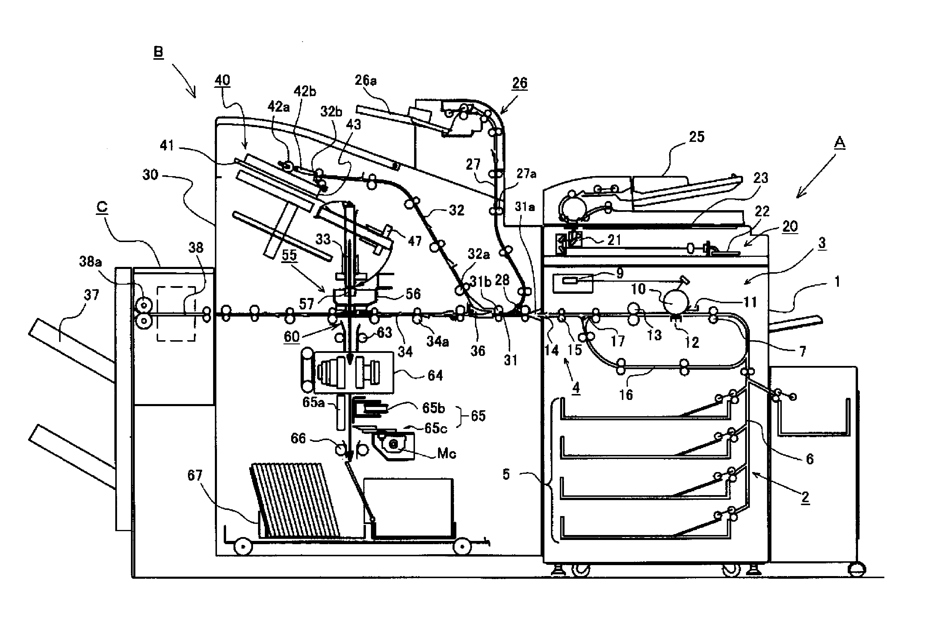
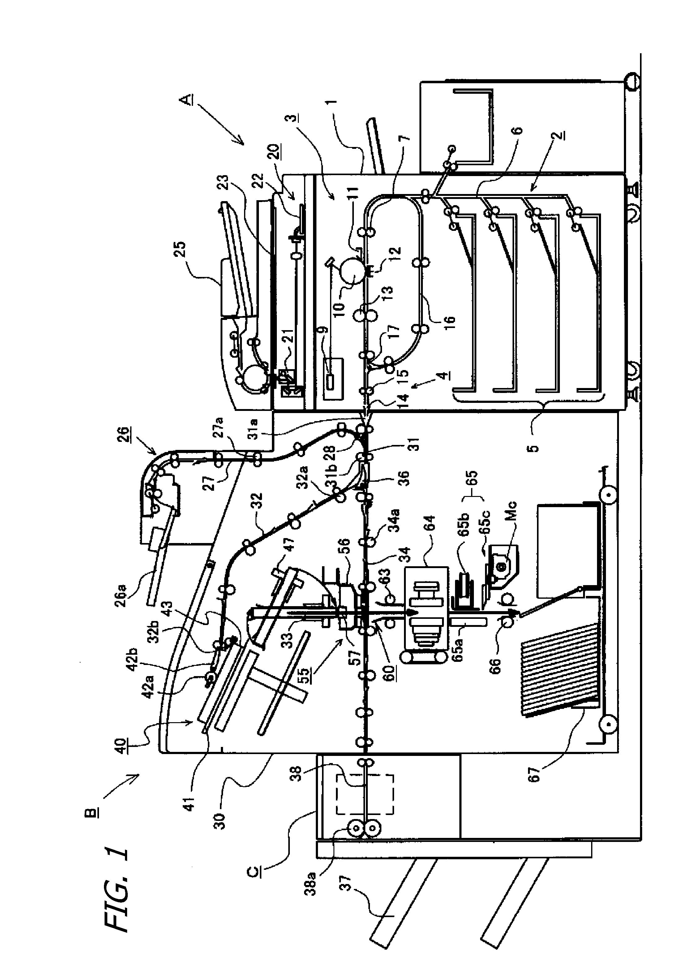
[0025]FIG. 1 is an explanatory view of an overall configuration of a bookbinding unit of the present invention and an image-forming system equipped with the same.
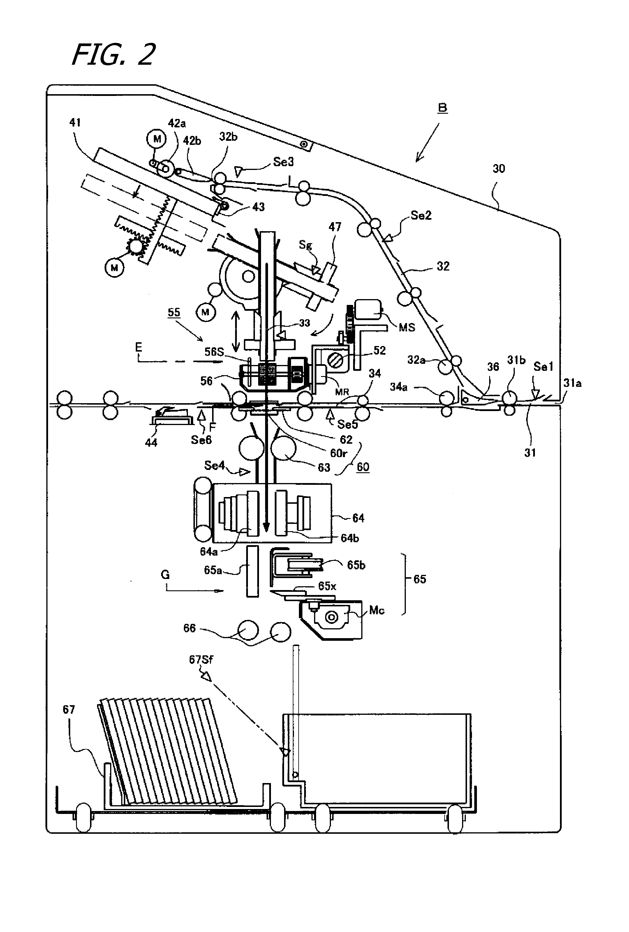
[0026]FIG. 2 is a detailed view of the bookbinding unit shown in FIG. 1.
[0027]FIGS. 3A and 3B show an adhesive application means in the apparatus shown in FIG. 2; FIG. 3A shows an overall configuration of an adhesive container; FIG. 3B is an explanatory view of the application of adhesive.
[0028]FIG. 4

Problems solved by technology

In particular, if excess adhesive is applied to the spine portion, it can leak out to the cover rear face, giving rise to a defectively bound booklet in which inner-bound leaves are adhered to the back side of the cover sheet.
Conversely, if an inadequate amount of adhesive is applied to the spine portion, it can become bent along the spine cover when the cover sheet is opened; either case will lead to problems with the quality of the booklet's appearance.
Along with these sorts of difficulties, if paper of thick caliper is used as a cover sheet, with the cover sheet not bending easily in opening a booklet after it has been bound, areas in the

Method used


Image

  • Bookbinding Method, and Bookbinding Unit and Image-Forming System Equipped with the Same
  • Bookbinding Method, and Bookbinding Unit and Image-Forming System Equipped with the Same
  • Bookbinding Method, and Bookbinding Unit and Image-Forming System Equipped with the Same

Examples


first embodiment

of Cover-Sheet Binding Means

[0054](See FIG. 5.) As shown in FIG. 5, the cover-sheet binding means 60 is disposed in the cover-sheet binding location F disposed downstream of the adhesive application position E. The cover-sheet binding means 60 is composed of a first pressing member 62a and a second pressing member 62b (collectively called pressing members 62); the pressing members 62 compose the shoulder pressing means 60p and the side pressing means 60q. The pressing members 62 are supported on guide rails (not shown) on the apparatus frame to be opposing on the left and right of the cover-sheet binding means 60. They are supported to approach and separate from each other between an idling position Wp and an operating position Ap. A control motor Mp1 is connected to the first pressing member 62a; a control motor Mp2 is connected to the second pressing member 62b. Specifically, rack gears 62r are integrally formed on the pressing members 62, and drive pinions 62p linked to the contr...

second embodiment

of Cover-Sheet Binding Means

[0062](See FIG. 10.) The following will now explain the second embodiment of the cover-sheet binding means 60 shown in FIG. 10. This embodiment is a configuration where the shoulder-portion pressing means and the flap-portion pressing means are separate members. The cover-sheet binding means 60 is disposed in the cover-sheet binding location F as shown in FIG. 10. This cover-sheet binding means 60 is composed of shoulder-portion pressing members 68a and 68b, and flap-portion pressing members 61a and 61b. Each of these is disposed in pairs on the left and right sides of the cover-sheet binding location F.

[0063]The left and right pair of shoulder-portion pressing members 68a, and 68b are supported by guide rails, not shown, of the apparatus frame to allow the left and right sides to mutually approach and separate. Also, the flap-portion pressing members 61a and 61b are matingly supported to slide on the guide rail 61g formed on the shoulder-portion pressing...


PUM

PropertyMeasurementUnit
Pressureaaaaaaaaaa

Abstract

Bookbinding unit that in binding an inner-leave sheet bundle together with a cover enables accurate binding of the cover onto the bundle's spine and meanwhile forms folding scores in the cover flaps. Furnished with: a stacking tray unit; a process path for sequentially transporting bundles from the tray unit into adhesive-application and cover-binding locations; an adhesive application unit, disposed in the adhesive-application location, that applies adhesive to bundles from the tray unit; a cover-supply unit that supplies covers to the cover-binding location; and a cover-binding unit, disposed in the cover-binding location, that binds sheet bundles from the adhesive-application location together with covers. The cover-binding unit has a shoulder-pressing unit that forms spine creases in the spine portion of the covers, and a flap-pressing unit that forms folds in the spine-creased sides of the covers.

Description

BACKGROUND OF THE INVENTION[0001]1. Technical Field[0002]The present invention, involving bookbinding units that collate sheets conveyed out of a photocopier, printer, or the like, into a bundle and cover the bundle with a cover sheet, relates to improvements in mechanisms for spine-creasing when encasing a bundle of inner-bound leaves with, and binding the bundle into, a cover sheet.[0003]2. Description of the Related Art[0004]With such bookbinding units generally, so-called perfect binding is known, in which sheets that are conveyed out of an imaging apparatus are stacked and collated into a bundle on a tray device, adhesive is applied to the spine part of the sheet bundle and the bundle is joined together with a cover sheet, into its central portion, in the form of an inverted T, and the cover sheet is spine-creased to close it onto the bundle.[0005]In conventional perfect binding techniques of this sort, forming folding scores in the flaps of the cover sheet is known, and is oft...

Claims


Application Information

Patent Timeline
IPC IPC(8): B42C13/00G03G21/16
CPCB65H2801/48G03G15/6544G03G2215/00936B65H45/30B42C11/04B42C13/003B65H37/04B42C9/0025
Inventor TAKAGI, KATSUMASASORITA, HIROYUKIYAMAKAWA, TAKEHIROKONDOU, JUNHARADA, TAKESHI
Owner NISCA KK
Why Eureka
Try Eureka