
Impingement cooled structure

Active Publication Date: 2009-02-05
IHI CORP +1
View PDF3 Cites 40 Cited by
  • Summary
  • Abstract
  • Description
  • Claims
  • Application Information

AI Technical Summary

Benefits of technology

[0018]In order to solve the above problems, the present invention was made. Specifically, an object of the present invention is, therefore, to provide an impingement cooled structure capable of reducing the amount of cooling air which cools hot walls of a turbine shroud and a turbine end wall, with a structure as simple as a structure of shrouds prior to Patent Documents 1 and 2.
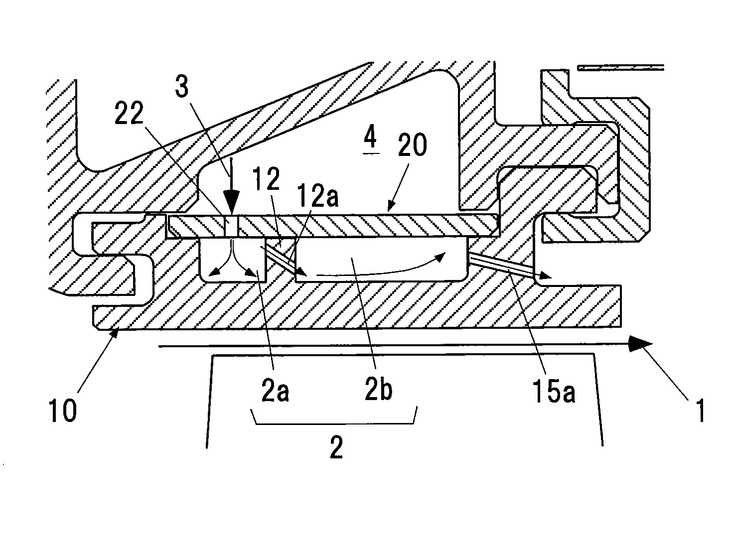
[0027]According to the aforementioned configuration of the present invention, the shroud cover has the first impingement cooling hole which allows cooling air to be jetted in the cavity formed between the shroud cover and shroud members, to cool the inner surface of the cavity by impingement. The shroud members each have the hole fin which divides the cavity into a plurality of the sub-cavities, and the hole fin has the second impingement cooling hole which allows the cooling air having flowed through the first impingement cooling hole to be jetted obliquely toward the bottom surface of the adjacent sub-cavity. Therefore, it is possible to reduce the amount of cooling air for cooling hot walls of a turbine shroud and a turbine end wall, with the thickness of the shroud members being the same as that of conventional ones, without increasing radial thickness of the entire shroud, by the structure simply having the hole fins that is as simple as a conventional structure.
[0028]That is, the cooled structure of the present invention is capable of significantly reducing the amount of cooling air by allowing cooling air, which is once used for impingement cooling to hot wall surfaces of the turbine shroud and end wall, to flow through an oblique hole (second impingement cooling hole) provided in the hole fin to re-use the cooling air for impingement cooling.

Problems solved by technology

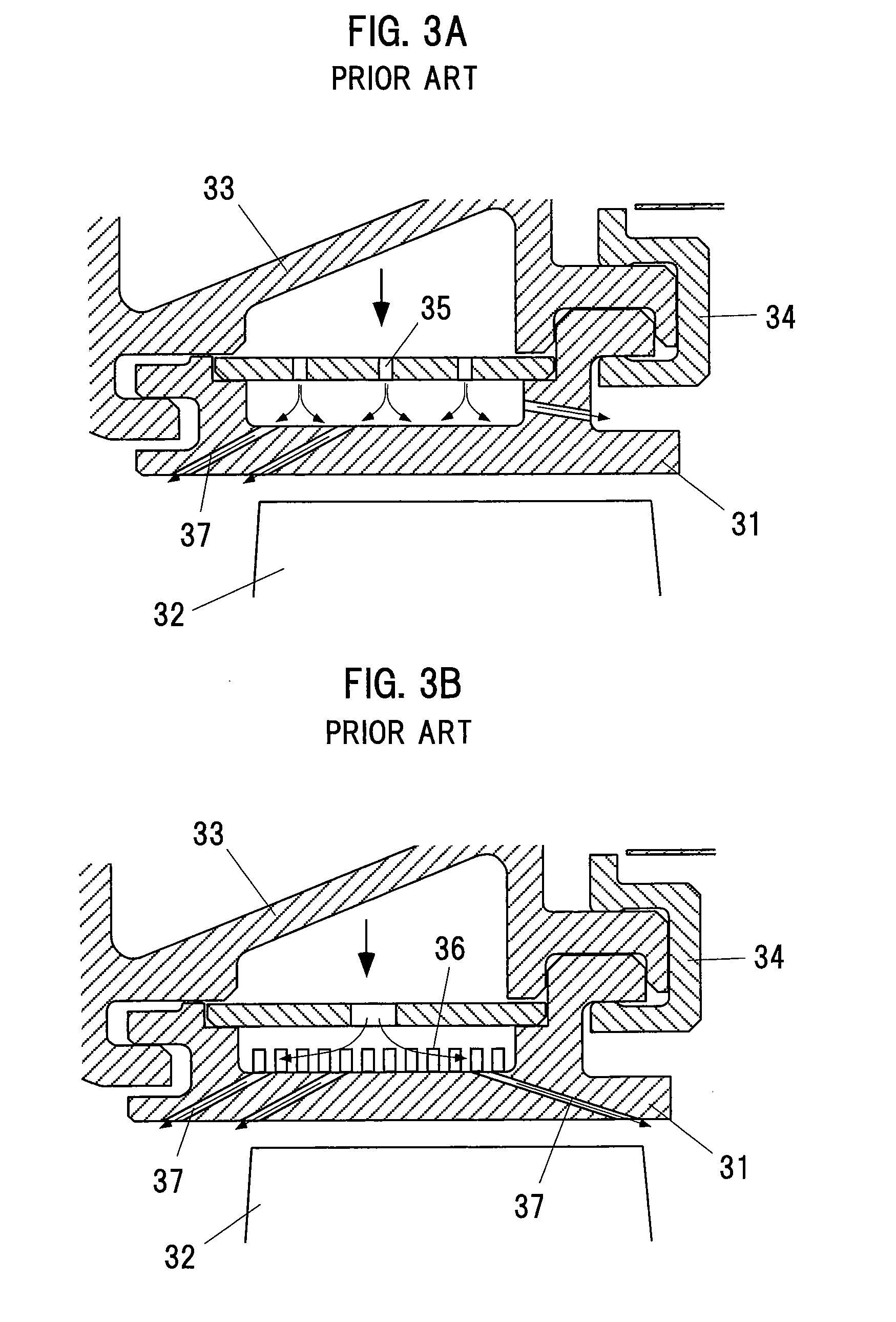
However, cooling air used in such a cooled structure is usually high pressure air compressed by a compressor.
Accordingly, there is a problem that the amount of the used cooling air directly affects engine performance.
The impingement cooled structures of Patent Documents 1 and 2, however, need to have a plurality of air chambers (cavities) which are stacked in the radial outward direction on top of each other, and thus, have a problem of an overall thickness greater than that of conventional shrouds.
In addition, these impingement cooled structures are complex as compared with shrouds prior to Patent Documents 1 and 2, causing a problem of an increase in manufacturing cost.

Method used


Image

  • Impingement cooled structure
  • Impingement cooled structure
  • Impingement cooled structure

Examples


first example

[0083]Test results obtained by comparing the cooling efficiency of the aforementioned structure of the present invention against that of conventional examples are described below.

[0084]As schematically shown in FIG. 14A, a test piece 5 which simulates a turbine shroud is produced. In a state in which hot gas 1 is flowed over one surface and cooling air 3 is flowed over the other surface, a metal surface temperature Tmg of the mainstream side of the test piece 5 is measured, and cooling efficiency η is calculated.

[0085]The cooling efficiency η is defined by the formula of η=(Tg−Tmg) / (Tg−Tc) . . . (1), where Tg is the hot mainstream air temperature and Tc is the cooling air temperature.

[0086]FIG. 14B shows a structure (multiple-stage oblique impingement) of the present invention used in the test, FIG. 14C shows a conventional example 1 (no pin, fin), and FIG. 14D shows a conventional example 2 (with pins). Other conditions are the same for all structures.

[0087]FIG. 15 shows test resul...

second example

[0089]Next, in the structure of the present invention, the influence of a gap at a fin tip is tested.

[0090]FIG. 16 is an illustrative diagram showing a relationship between a gap Δh between a radial outward end of a hole fin 12 and an inner surface of a shroud cover 20, and a height h of the hole fin. In the drawing, the value (Δh / h) obtained by dividing the gap Δh between the fin tip and the plate by the fin height h is set to range from 0 (no gap) to 0.2, and a calculation of a cooling air flow rate and a heat transfer analysis are performed.

[0091]FIG. 17 shows the analysis results. The horizontal axis represents the axial length and the vertical axis represents the metal temperature of a gas passing surface (metal surface temperature on the mainstream side). Lines in the drawing represent results for Δh / h ranging from 0 to 0.2.

[0092]From the graph, it is found that the temperature of the turbine shroud stands below an allowable value when Δh / h stands at or below about 0.2.

third example

[0093]Next, in the structure of the present invention, the influence of the angle of a second impingement cooling hole 12a is tested.

[0094]FIG. 18 is an illustrative diagram showing a relationship between the angle θ of the second impingement cooling hole 12a and the height e of an impingement. In the drawing, a cooling performance test is conducted under the following conditions: the angle θ=30° and 45°, and h / L=0.13 and 0.26, where h is the height of an impingement, and L is cooling chamber length.

[0095]FIG. 19 shows the test results. The horizontal axis represents the cooling air flow rate, and the vertical axis represents the average cooling efficiency. Solid circles and open circles in the graph represent the test results for 30° and 45°, respectively.

[0096]From the graph, it is found that even if the angle is changed, the cooling efficiency is not much affected thereby.


PUM


Abstract

An impingement cooled structure includes a plurality of shroud members disposed in a circumferential direction to constitute a ring-shaped shroud surrounding a hot gas stream, and a shroud cover mounted on radial outside faces of the shroud members to form a cavity therebetween. The shroud cover has a first impingement cooling hole which communicates with the cavity and allows cooling air to be jetted to an inside thereof so as to cool an inner surface of the cavity by impingement. The shroud members each has a hole fin. The hole fin divides the cavity into a plurality of sub-cavities. Further, the hole fin has a second impingement cooling hole which allows the cooling air having flowed through the first impingement cooling hole to be jetted obliquely toward a bottom surface of the sub-cavity adjacent thereto.

Description

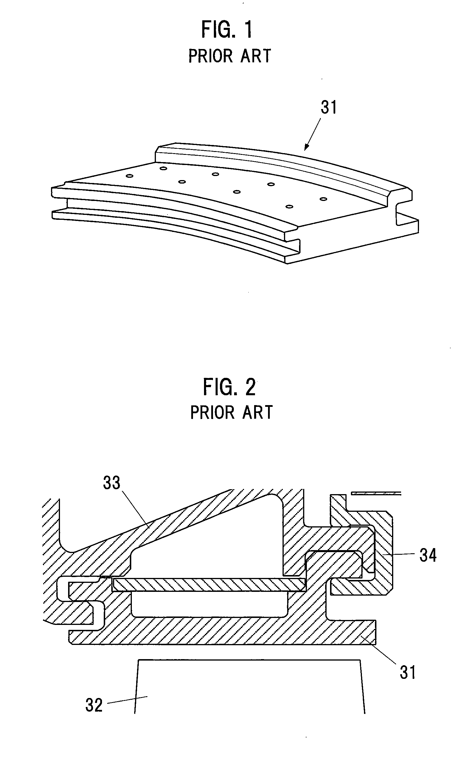
BACKGROUND OF THE INVENTION[0001]1. Technical Field of the Invention[0002]The present invention relates to an impingement cooled structure that cools hot walls of a turbine shroud and a turbine end wall.[0003]2. Description of the Related Art[0004]In recent years, in order to improve thermal efficiency, an increase in the temperature of a gas turbine has been promoted. In this case, the turbine inlet temperature reaches about 1200° C. to 1700° C. Under such high temperatures, metal turbine components need to be cooled so as not to exceed the service temperature limit of the materials thereof.[0005]An example of such turbine components includes a turbine shroud 31 shown in FIG. 1. As shown in a cross-sectional view of FIG. 2, a plurality of turbine shrouds 31 are connected to each other in a circumferential direction to form a ring shape and surround fast-rotating turbine blades 32 such that the ring shape is spaced from the tip surfaces of the turbine blades 32. With this structure,...

Claims


Application Information

Patent Timeline
IPC IPC(8): F01D25/12F02C7/18
CPCF01D11/24F01D25/246F05D2240/11F05D2260/202F01D11/08F05D2260/2212F05D2260/2214F05D2260/201
Inventor FUJIMOTO, SHUOHKITA, YOUJIFUKUYAMA, YOSHITAKAYAMANE, TAKASHIMATSUSHITA, MASAHIROYOSHIDA, TOYOAKI
Owner IHI CORP
Learn More