
Flat cable covering means for generating different impendances

a technology of flat cable and covering means, which is applied in the direction of cables, insulated conductors, conductors, etc., can solve the problems of high cost of molds and labor, complicated assembly process, and increased complexity of computer or television structure, so as to simplify manufacturing and assembly processes, simple and convenient line managemen

Inactive Publication Date: 2009-02-05
JESS-LINK PRODUCTS
View PDF2 Cites 10 Cited by
  • Summary
  • Abstract
  • Description
  • Claims
  • Application Information

AI Technical Summary

Benefits of technology

The present invention provides a flat cable covering that can generate different impedances. This means that different devices in an electronic apparatus can have different impedances without needing separate cables. This simplifies the manufacturing and assembly processes and makes managing and laying lines easier. The flat cable covering has multiple cores arranged at an interval, an insulating body that covers the outer surface of the cores, and a first metallic covering layer that partially covers one side of the insulating body with the impedance of the cores in the area covered by the first metallic covering layer being smaller than that of the cores in the area not covered by the first metallic covering layer.

Problems solved by technology

Since electronic apparatuses are getting more and more precise, the structure of a computer or television also becomes much more delicate.
However, in practice, the conventional flat cable covering means still has some drawbacks as follows.
Further, when the conventional flat cable covering means is inserted into the connector, it always takes a lot of time in assembly.
In addition to the cost of mold and labor, the arrangement of transmission lines applied to different devices within the electronic apparatus becomes more complicated.

Method used


Image

  • Flat cable covering means for generating different impendances
  • Flat cable covering means for generating different impendances
  • Flat cable covering means for generating different impendances

Examples


Embodiment Construction

[0013]The detailed description and technical contents of the present invention will be explained with reference to the accompanying drawings. However, the drawings are illustrative only and are not used to limit the scope of the present invention.

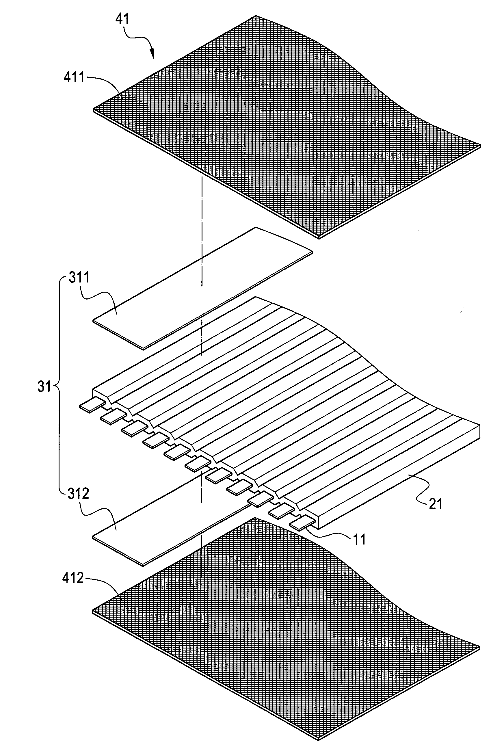
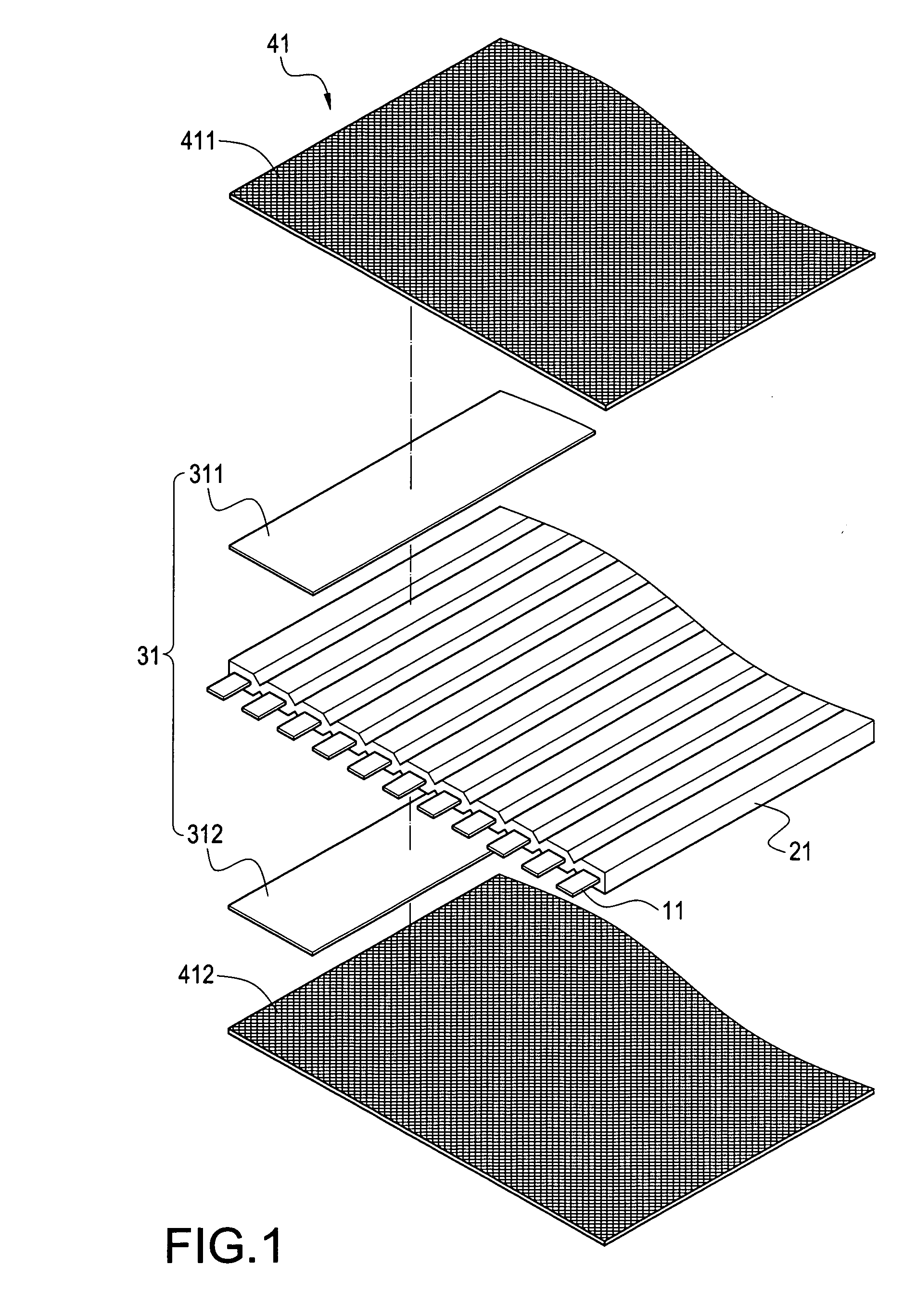
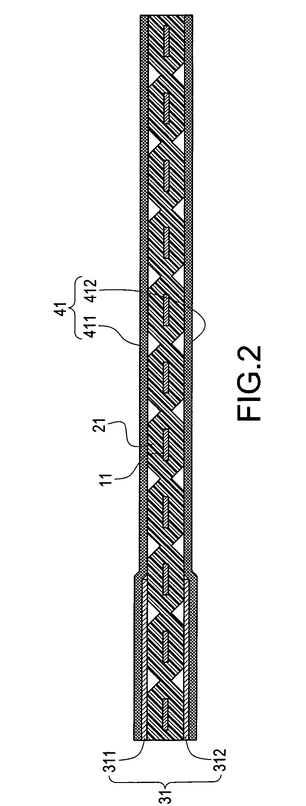
[0014]FIG. 1 is an exploded perspective view showing the first embodiment of the present invention, and FIG. 2 is an assembled cross-sectional view of the present invention. The present invention provides a flat cable covering means for generating different impedances, which includes a plurality of cores 11, an insulating body 21 and a first metallic covering layer 31.

[0015]The core 11 is made of metallic materials having good electric conductivity. The core can be made from single copper wire, copper piece, or copper coil, or it can be made by twisting a plurality of copper wires. The cores 11 are provided respectively at the same interval and in parallel to one another. Since the core 11 is conventional and has a large number of forms, th...


PUM

PropertyMeasurementUnit
impedanceaaaaaaaaaa
impedanceaaaaaaaaaa
impedancesaaaaaaaaaa

Abstract

A flat cable covering means for generating different impedances includes a plurality of cores, an insulating body and a first metallic covering layer. The cores are arranged at an interval respectively. The insulating body covers an outer surface of the cores. The first metallic covering layer is provided to correspond to a portion of cores and partially covers one side of the insulating body with the impedance of the cores in an area covered by the first metallic covering layer smaller than that of the cores in an area not covered by the first metallic covering layer. Via this arrangement, in order to correspond to the need of impedances of different devices in the electronic apparatus, the different impedances can be made integrally in the same flat cable. In this way, not only the manufacturing and assembling processes can be simplified, but also the management and layout of lines are simple and convenient.

Description

BACKGROUND OF THE INVENTION[0001]1. Field of the Invention[0002]The present invention relates to a flat cable covering means, and in particular to a flat cable covering means for generating different impedances.[0003]2. Description of Prior Art[0004]Since electronic apparatuses are getting more and more precise, the structure of a computer or television also becomes much more delicate. Thus, a flat cable is applied in the above electronic apparatus to transmit signals, so that the manufacturer or user can attach the flat cable to a connector rapidly. With a row-like structure of the flat cable, the arrangement within the space of the computer or television is neat and clear so as to facilitate the dissipation of the heat generated. Further, the maintenance of the electronic apparatus can be performed easily, thereby keeping a good effect of transmitting signals.[0005]The conventional flat cable covering means is constituted of a plurality of copper cores and an insulating body made ...

Claims


Application Information

Patent Timeline
Patent Type & Authority Applications(United States)
IPC IPC(8): B32B15/00B32B15/20
CPCY10T428/12549H01B7/0861
Inventor CHIANG, CHIN-CHIH
Owner JESS-LINK PRODUCTS
Learn More