Method of starting fuel cell system

a fuel cell and fuel cell technology, applied in the direction of fuel cells, fuel cell components, fuel cell grouping, etc., can solve the problems of reducing the operation efficiency and lifetime of the pemfc, and affecting the efficiency of the pem

Active Publication Date: 2009-02-05
SAMSUNG ELECTRONICS CO LTD
View PDF4 Cites 3 Cited by
  • Summary
  • Abstract
  • Description
  • Claims
  • Application Information

AI Technical Summary

Benefits of technology

[0010]Aspects of the present invention provide a method to rapidly increase an internal temperature of a fuel cell stack of a fuel cell system, during a start-up (preheating) operation of the fuel cell system.

Problems solved by technology

However, a conventional PEMFC has problems, due to the low operating temperature of approximately 100° C., or less.
When the catalyst is poisoned by CO, an electrochemical activity of the catalyst is greatly reduced, and as a result, the operation efficiency and lifetime of the PEMFC are significantly reduced.
Furthermore, as the operating temperature of a conventional PEMFC is decreased, the catalyst poisoning by the CO is increased.
However, a conventional high temperature PEMFC requires a cooling system to cool a fuel cell stack thereof.
However, due to the time required for the coolant to be heated, the normal operation of the PEMFC is delayed.

Method used


Image

  • Method of starting fuel cell system
  • Method of starting fuel cell system
  • Method of starting fuel cell system

Examples


Embodiment Construction

[0024]Reference will now be made in detail to the present embodiments of the present invention, examples of which are illustrated in the accompanying drawings, wherein like reference numerals refer to the like elements throughout. The embodiments are described below in order to explain the present invention by referring to the figures.

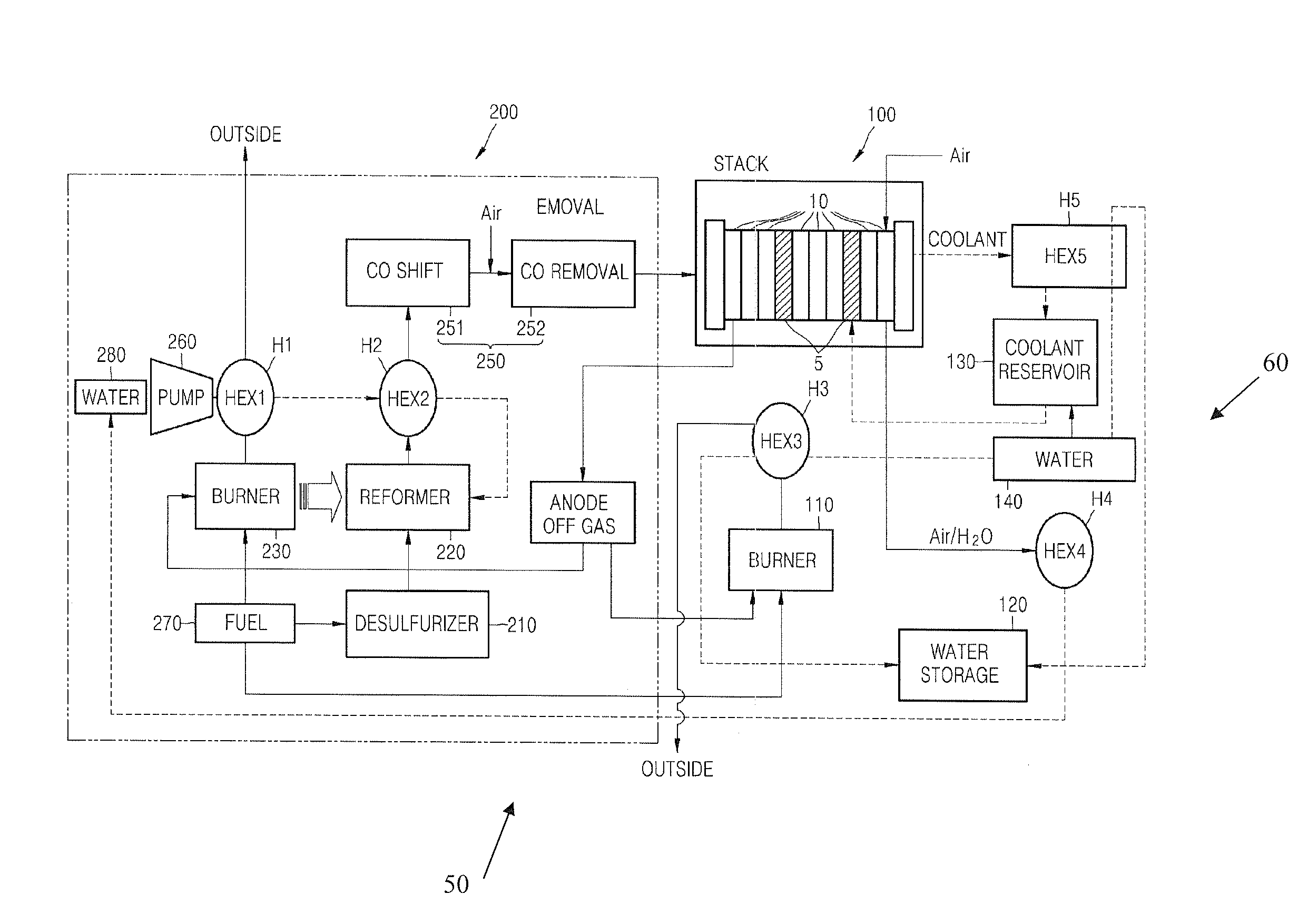
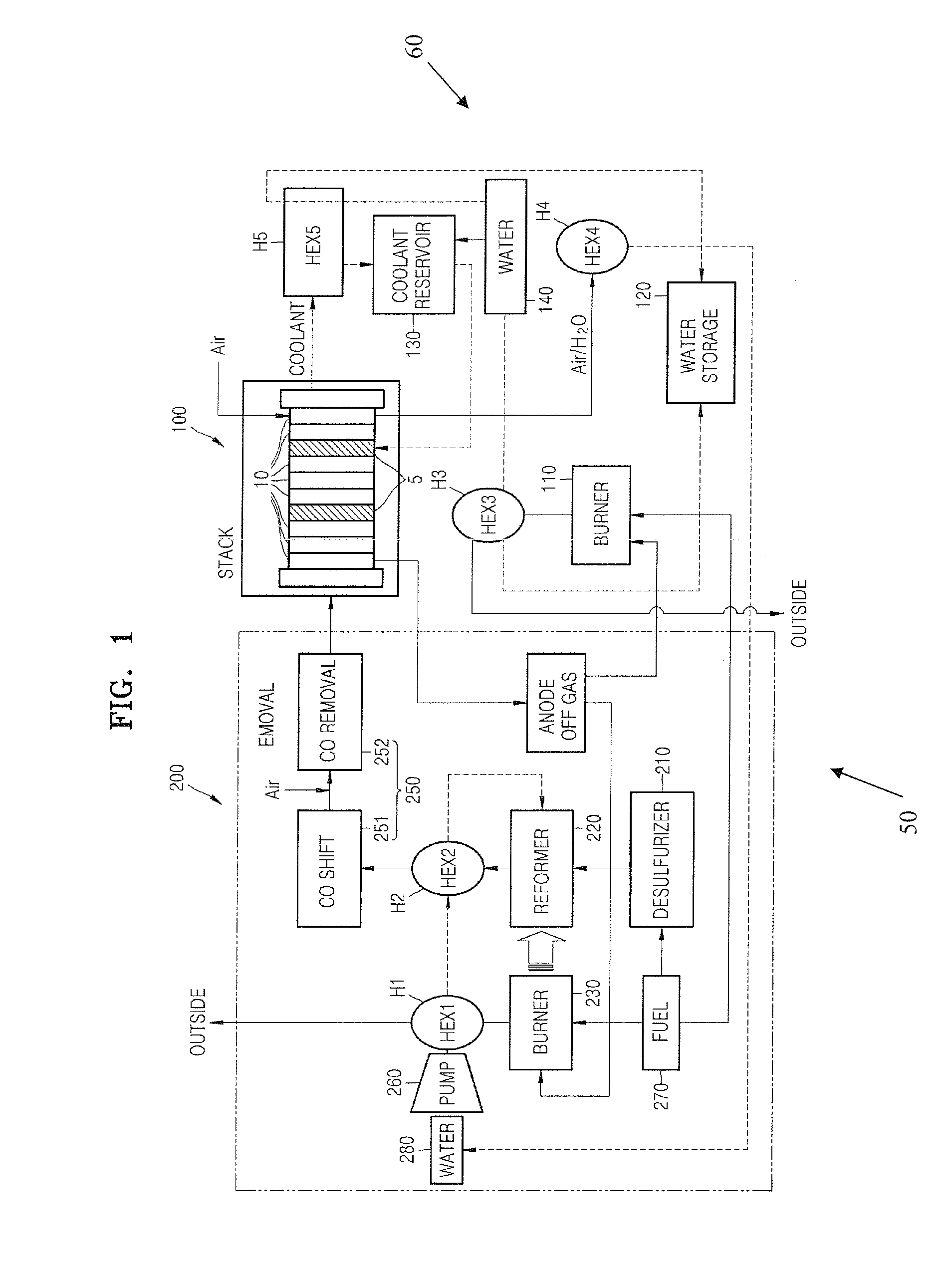
[0025]FIG. 1 is a block diagram of a fuel cell system 50, according to an exemplary embodiment of the present invention. Referring to FIG. 1, the fuel cell system 50 includes a fuel processor 200, a polymer electrolyte membrane fuel cell (PEMFC) stack 100, and a cooling system 60 to cool the PEMFC stack 100.

[0026]The fuel processor 200 includes a desulfurizer 210, a reformer 220, a burner 230, a water supply pump 260, first and second heat exchangers H1 and H2, and a carbon monoxide (CO) removing unit 250. The CO removing unit 250 comprises a CO shift reactor 251 and a CO remover 252.

[0027]Hydrogen is generated in the reformer 220, which is heated by t...


PUM

PropertyMeasurementUnit
temperatureaaaaaaaaaa
operating temperatureaaaaaaaaaa

Abstract

Provided is a method of starting a polymer electrolyte membrane fuel cell (PEMFC) stack by rapidly increasing the temperature of the PEMFC stack. The PEMFC stack includes: a first flow line that is connected to upper parts of cooling plates installed in a plurality of unit cells of the PEMFC stack; a second flow line that is connected to lower parts of the cooling plates; a coolant reservoir installed between the first flow line and the second flow line; a heat exchanger installed between the first flow line and the coolant reservoir; a by-pass line that connects a point between the coolant reservoir and the second flow line, to the first flow line; a heating element that heats coolant in the by-pass line; a first valve installed between the first flow line and the heat exchanger; and a second valve that selectively connects the coolant reservoir, the second flow line, and the by-pass line. The method of starting a PEMFC stack includes: closing the first valve and controlling the second valve so that the second flow line and the by-pass line are connected to each other, and the coolant in the coolant reservoir is not connected to the second flow line and the by-pass line; and increasing the temperature of the PEMFC stack by heating the coolant in the by-pass line, using the heating element.

Description

CROSS-REFERENCE TO RELATED APPLICATIONS[0001]This application claims the benefit of Korean Application No. 2007-7237, filed Jan. 23, 2007, in the Korean Intellectual Property Office, the disclosure of which is incorporated herein by reference.BACKGROUND OF THE INVENTION[0002]1. Field of the Invention[0003]Aspects of the present invention relate to a fuel cell, a fuel cell system, and a method of operating the same.[0004]2. Description of the Related Art[0005]A fuel cell is an electricity generation device that directly converts the chemical energy of hydrogen, included in a hydrocarbon material, such as, methanol, ethanol, or natural gas, into electrical energy through a chemical reaction with oxygen.[0006]A polymer electrolyte membrane fuel cell (PEMFC) has a wide range of applications, for example, as a power source for automobiles, as a distributional power source for houses or public buildings, and as a small power source for electronic devices. A PEMFC has a superior power outp...

Claims


Application Information

Patent Timeline
Patent Type & Authority Applications(United States)
IPC IPC(8): H01M2/00
CPCH01M8/04029Y02E60/50H01M8/04268H01M8/04
Inventor SONG, TAE-WONOH, DUK-JINLEE, HYUN-CHULKIM, DONG-KWANWANG, YONG
Owner SAMSUNG ELECTRONICS CO LTD
Why Eureka
Try Eureka