
Medical manipulator system

a manipulator and manipulator technology, applied in the field of medical manipulators, can solve problems such as the unit and the base end pulley

Active Publication Date: 2009-02-05
KARL STORZ GMBH & CO KG
View PDF10 Cites 35 Cited by
  • Summary
  • Abstract
  • Description
  • Claims
  • Application Information

AI Technical Summary

Benefits of technology

[0018]The present invention has the object of providing a medical manipulator system, which enables the changing of operational modes and detachment of a connector or the like to be suitably controlled.
[0020]By providing such an indicator, the operator can easily confirm at least the operational mode and the stopped mode, and therefore surgical operations can be carried out efficiently. Switching of the illumination state may be defined as switching between an illuminated and a non-illuminated state, switching between continuous illumination and a flashing state, switching a flashing cycle, switching the illumination brightness, or the like.
[0022]In this manner, in the case of the operational mode, by means of the lock mechanism locking the connector that interconnects the operating unit and the controller, the connector cannot be inadvertently pulled out and disconnected.

Problems solved by technology

Because of the necessity to easily clean and disinfect the working unit periodically, the working unit does not contain any electronic components such as sensors or the like, and the positions and origin points of the distal end working unit and the base end pulleys cannot be detected directly.

Method used


Image

  • Medical manipulator system
  • Medical manipulator system
  • Medical manipulator system

Examples


Embodiment Construction

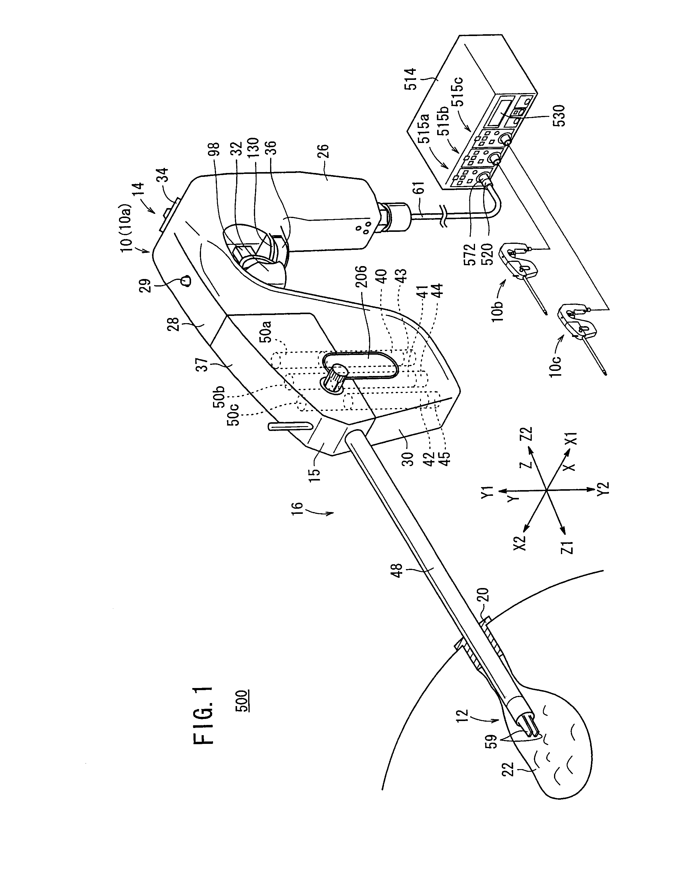
[0034]Descriptions of a medical manipulator system 500 according to an embodiment of the present invention shall be presented below with reference to the accompanying FIGS. 1 through 10. The manipulator system 500 (see FIG. 1) is intended for medical use, and in particular is utilized for performing laparoscopic surgeries and the like.

[0035]As shown in FIG. 1, the manipulator system 500 includes a manipulator 10 and a controller 514.

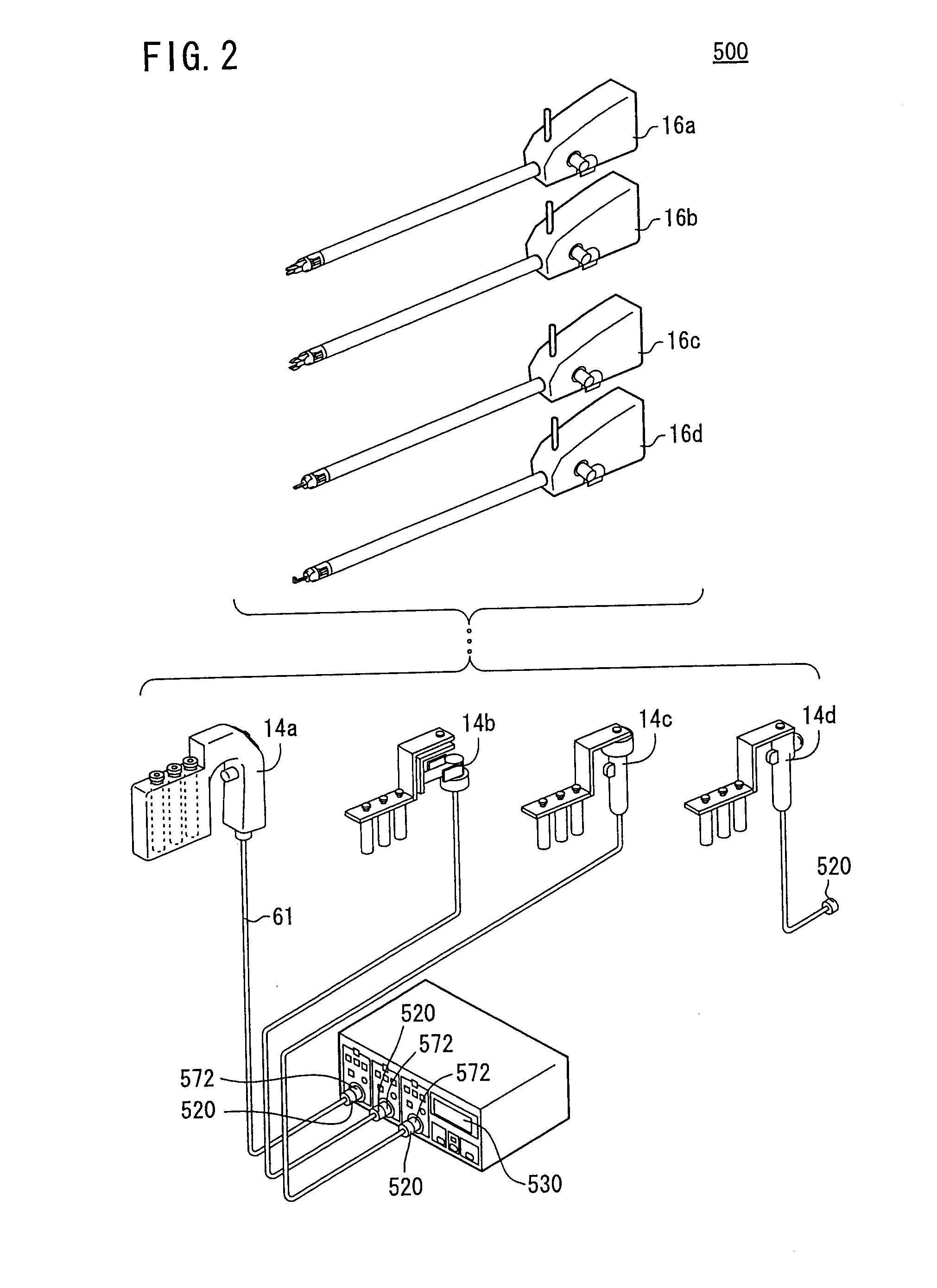
[0036]To interconnect the manipulator 10 and the controller 514, a detachable connector 520 is provided.

[0037]A distal end working unit (end effector) 12 of the manipulator 10 carries out predetermined procedures for gripping a portion of a living body or a curved needle, or the like. The basic structure of the manipulator 10 is made up from an operating unit 14 and a working unit 16. The controller 514 serves to carry out electrical controls for the manipulator 10, and is connected through a connector 520 with respect to a cable 61 that extends from a l...


PUM


Abstract

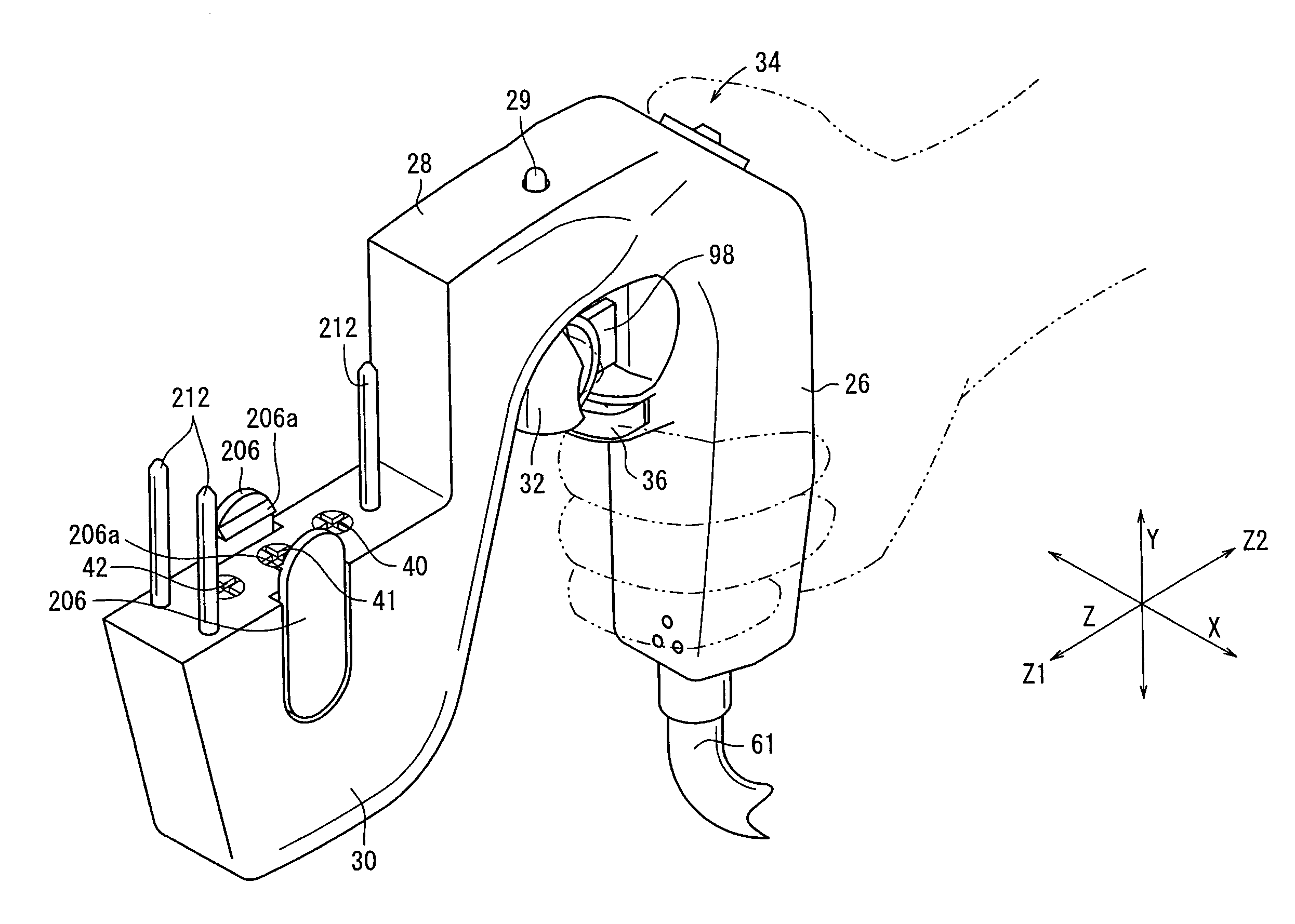
A medical manipulator system includes a medical manipulator, an operating unit for inputting operation commands, motors for driving a working unit, a controller for driving the motors based on operation commands supplied from the operating unit, and an LED that displays an operational state. The controller carries out controls for distinguishing between an operational mode in which the operation command is validated and the motors are driven, and a stopped mode in which the motors are halted regardless of whether the operation command is present or not. An illumination state of the LED is switched dependent on whether the system is in the operational mode or the stopped mode. The LED is disposed in the center of an upper surface of a bridge, which interconnects a grip handle and an actuator block.

Description

BACKGROUND OF THE INVENTION[0001]1. Field of the Invention[0002]The present invention relates to a medical manipulator system by which a predetermined working unit performs movements and operations based on operation commands input from an operating unit.[0003]2. Description of the Related Art[0004]In laparoscopic surgery, a number of small holes are opened in a patient's abdomen or the like, and an endoscope, a forceps (or manipulator) or the like is inserted, and surgery is carried out while the surgeon observes an image from the endoscope on a monitor. In this type of laparoscopic surgery, owing to the fact that opening of the abdominal cavity is unnecessary, the burden on the patient is small, and number of days for the post-operative recovery and number of days spent in the hospital can be significantly reduced. Therefore, laparoscopic surgical operations are expected to find an increased range of applications.[0005]A manipulator system, for example, as disclosed in Japanese La...

Claims


Application Information

Patent Timeline
IPC IPC(8): A61B19/00
CPCA61B19/22A61B2017/00115A61B2019/4836A61B2019/2242A61B2017/0046A61B34/70A61B34/71A61B2090/0807
Inventor OMORI, SHIGERU
Owner KARL STORZ GMBH & CO KG
Learn More