Pulsation Attenuation

a technology of attenuation and compression, applied in the direction of positive displacement liquid engines, liquid fuel engines, couplings, etc., can solve the problems of reducing compressor efficiency and flow capacity, significant system pressure loss, and possible pressure loss, so as to improve pump efficiency and improve pump pressure. the effect of pressur

Active Publication Date: 2009-02-12
OPTIMUM POWER TECH LP
View PDF14 Cites 32 Cited by
  • Summary
  • Abstract
  • Description
  • Claims
  • Application Information

AI Technical Summary

Benefits of technology

[0022]In an embodiment, a pump efficiency improvement device is provided. The pump efficiency improvement device includes a first junction, a second junction, a first branch, a second branch, and a header. The first junction has a main connector, a first branch connector, and a second branch connector. The second junction has a main connector, a first branch connector, and a second branch connector. The first branch has a first end coupled to the first branch connector of the first junction and a second end coupled to the first branch connector of the second junction. The second branch has a first end coupled to the second branch connector of the first junction and a second end coupled to the second branch connector of the second junction. The header has a first end coupled to the pump and a second end coupled to the main connector of the first junction, the header having a length that improves pressure at the pump.

Problems solved by technology

However, those approaches generally result in significant system pressure losses on both the suction and discharge sides of the compressor, reducing compressor efficiency and flow capacity.
These devices accomplish pulsation control by adding resistance, or damping, to the system, and they result in pressure losses that may exist both upstream and downstream of the compressor cylinders.
For common pipeline transmission applications, particularly those having low pressure ratios, such as natural gas pipeline systems, pressure losses can noticeably degrade system operating efficiency.
As larger high-speed compressors have been increasingly applied to pipeline transmission applications, these influences are thought to have become more detrimental to performance, due to the higher frequency pulsations that must be damped.
However, the above method does not effectively attenuate the 4th harmonic, i.e., the noise component having a frequency four times the main noise component, nor any other harmonics divisible by 4.
Such an arrangement furthermore operates on a single primary frequency and certain of its harmonics and so is unlikely to provide effective noise attenuation over a range of noise frequencies.

Method used


Image

  • Pulsation Attenuation
  • Pulsation Attenuation
  • Pulsation Attenuation

Examples


Embodiment Construction

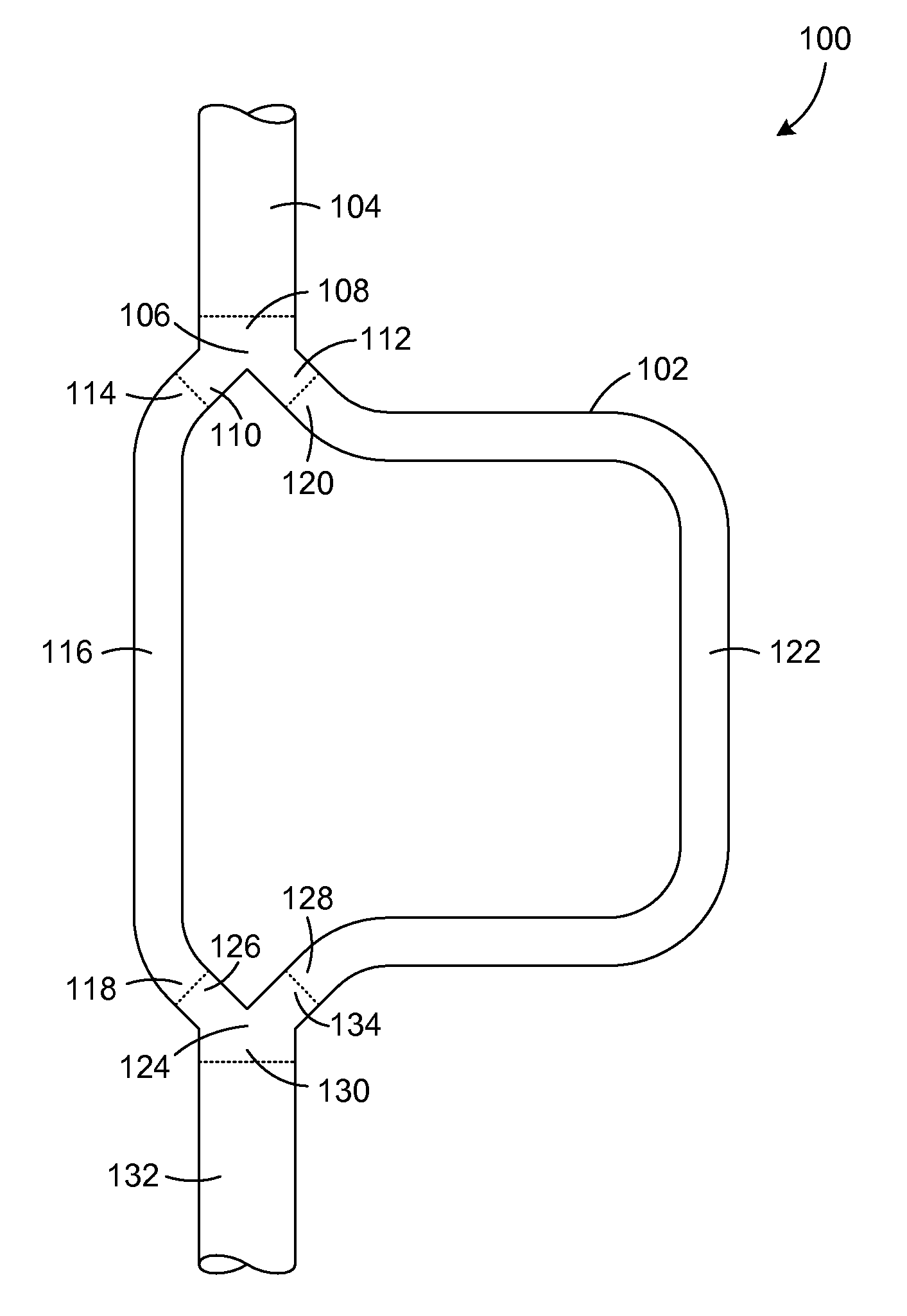
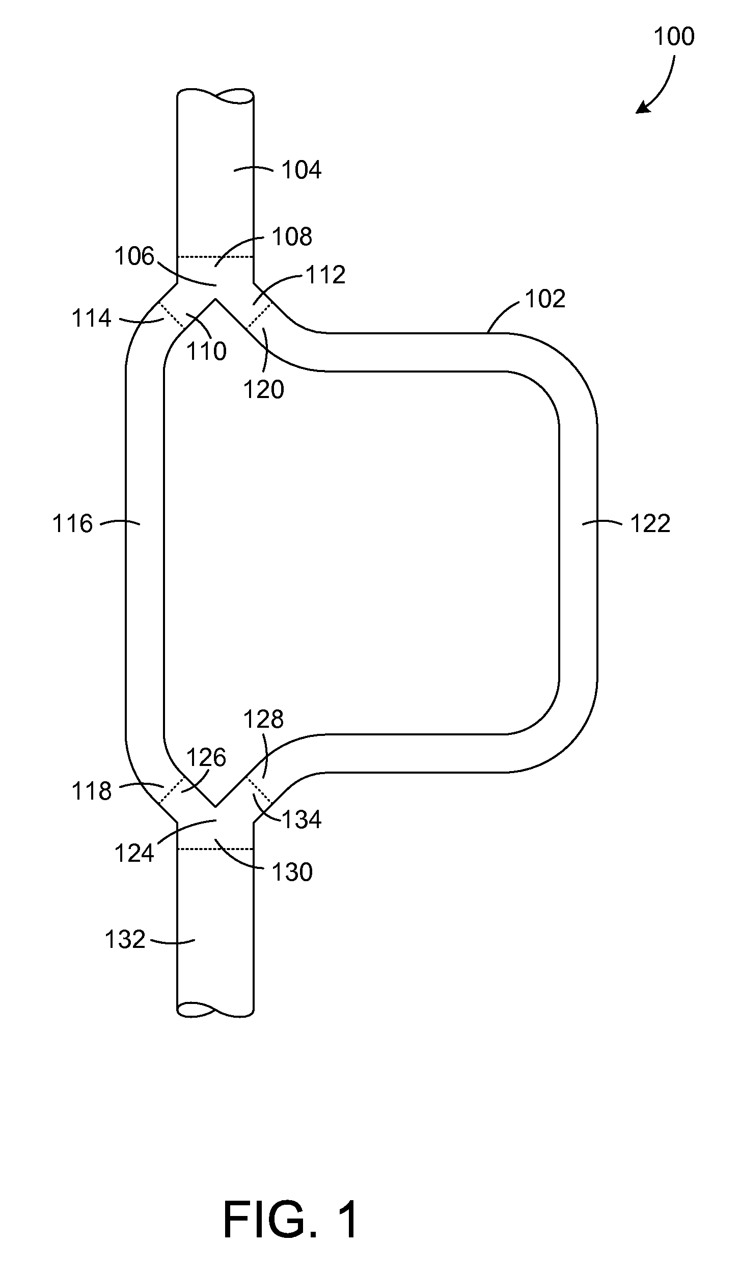
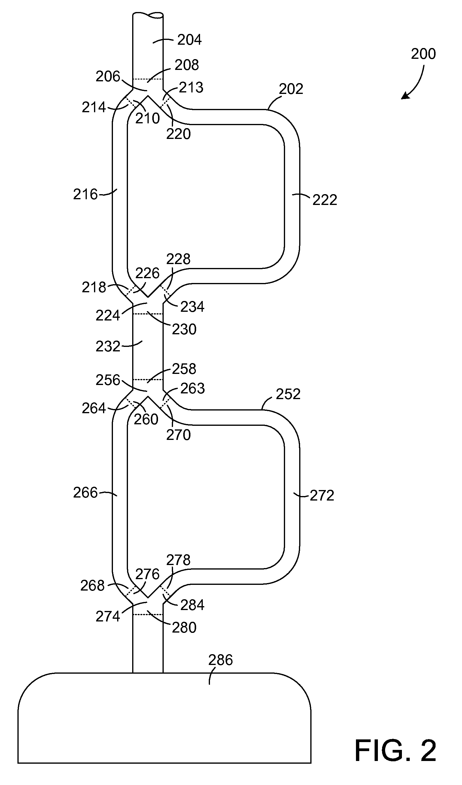
[0033]Reference will now be made to embodiments of pulsation attenuation apparatuses, networks, and methods, examples of which are illustrated in the accompanying drawings. Details, features, and advantages of pulsation attenuation will become further apparent in the following detailed description of embodiments thereof. It is to be understood that the figures and descriptions included herein illustrate and describe elements that are of particular relevance to pulsation attenuation apparatuses, networks, and methods, while eliminating, for purposes of clarity, other elements found in typical fluid pumping systems.

[0034]Systems, apparatuses, and methods to perform pulsation attenuation are described herein. Any reference in the specification to “one embodiment,”“a certain embodiment,” or any other reference to an embodiment is intended to indicate that a particular feature, structure or characteristic described in connection with the embodiment is included in at least one embodiment ...


PUM


Abstract

A system, apparatus, and method for attenuating pulsations in a pumping system.

Description

CROSS-REFERENCE TO RELATED APPLICATIONS[0001]The present application claims priority to U.S. provisional patent application No. 60 / 954,914, filed Aug. 9, 2007, which is incorporated herein in its entirety and is currently pending.FIELD OF THE INVENTION [0002]The present invention is concerned with reducing pulsations in fluid systems. An embodiment of the invention also increases fluid flow over traditional systems, resulting in smoother, more efficient fluid flow in a closed system.BACKGROUND OF THE INVENTION [0003]A fluid, whether gaseous or liquid, may flow through a conduit or duct. The fluid may be propelled by a pressure creating device, such as a compressor or other type of pump. One type of compressor used to propel fluid, particularly gas, is a reciprocating compressor. Effective control of the pressure pulsations generated by reciprocating compressors is desirable to prevent damaging shaking forces and stresses in system piping, vessels, and mechanical equipment and struct...

Claims


Application Information

Patent Timeline
Patent Type & Authority Applications(United States)
IPC IPC(8): F17D1/00
CPCF01C21/006F02B33/44F04C2270/12F04B53/001F16L55/04Y02T10/17F04C2270/14Y10T137/87265Y10T137/0318Y02T10/12F04B11/0091F04B39/0055
Inventor CHATFIELD, GLEN F.CRANDALL, JOHN G.
Owner OPTIMUM POWER TECH LP
Why Eureka
Try Eureka