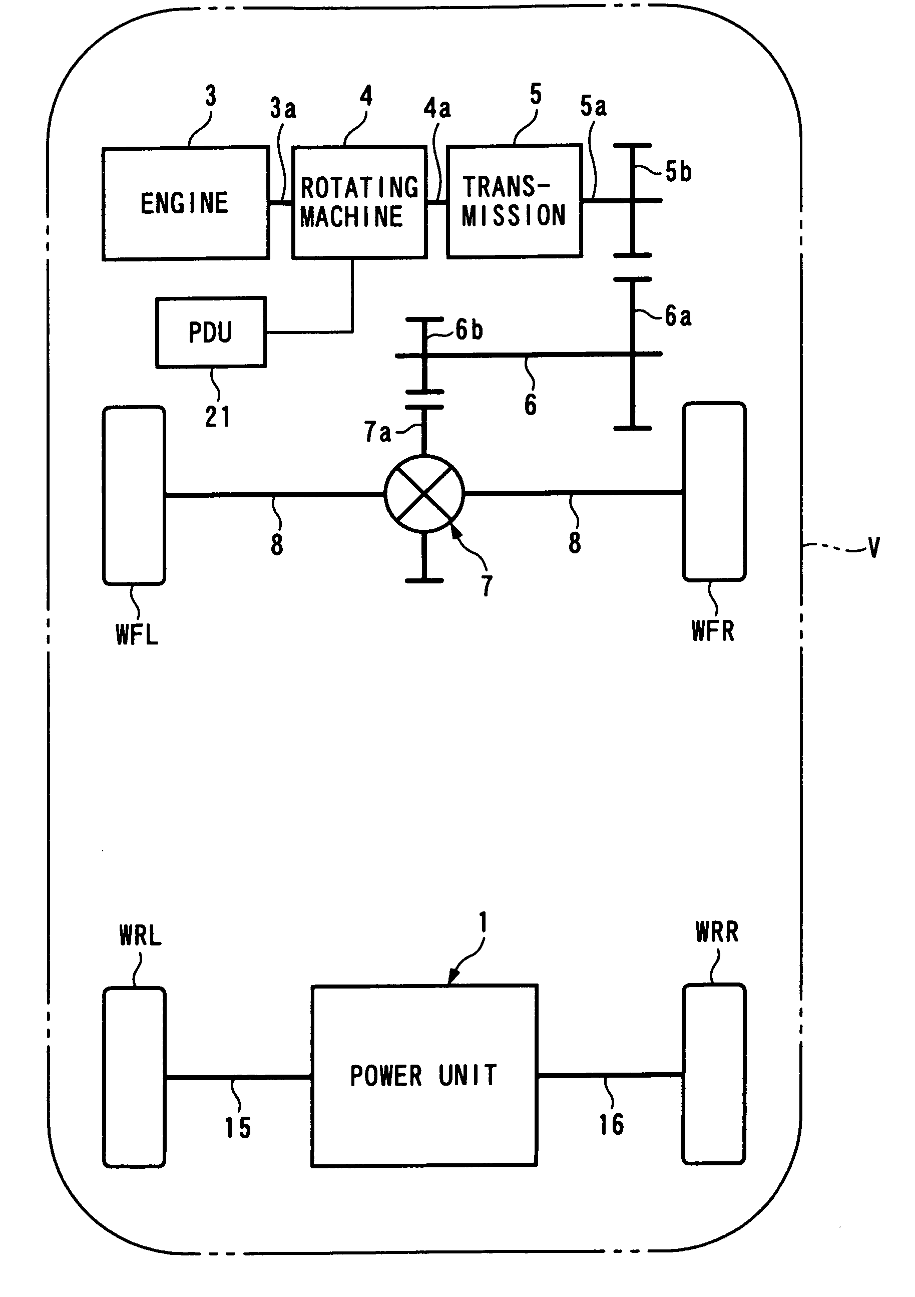
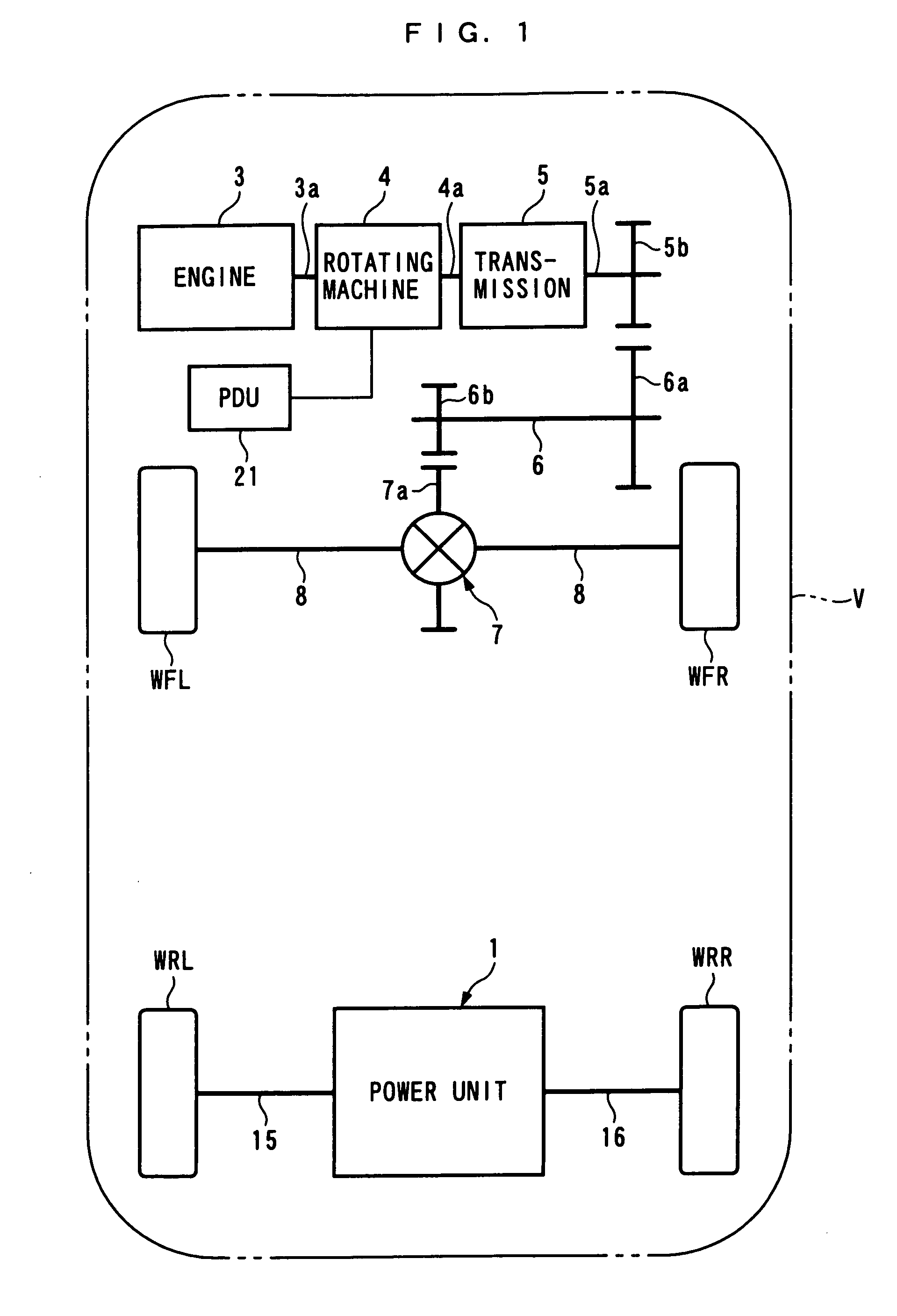
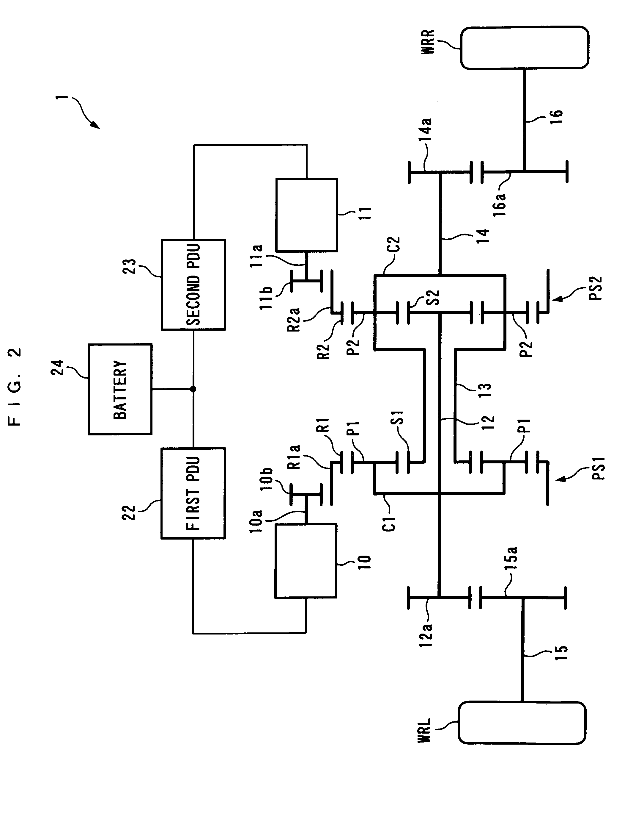
[0033]With the arrangement of this preferred embodiment, the first to three elements capable of transmitting energy to each other, having respective rotational speeds satisfying a collinear relationship, and configured such that the first to third elements are in a line in order in a collinear chart representing the collinear relationship, the fourth to sixth elements configured similarly, the first and second energy input and output devices, and the left and right driven parts are connected in the following manner: The first and fifth elements are connected to the right driven part, the second and fourth elements to the left driven part, and the third and sixth elements to the first and second energy input and output devices, respectively. Since the first to third elements of which the rotational speeds are in a collinear relationship and the fourth to sixth elements of which the rotational speeds are in a collinear relationship are connected to the first and second energy input and output devices and the left and right driven parts, as described above, as shown in FIG. 28, the first energy input and
output device, the left driven part, the right driven part, and the second energy input and
output device are in a collinear relationship in respect of rotational speed, and are in a line in a collinear chart representing the collinear relationship. Therefore, it is possible to obtain the above-described advantageous effects.
[0034]More preferably, the first energy transmission device is a first planetary gear unit having a first sun gear, a first ring gear, and a first carrier rotatably supporting a first planetary gear in mesh with the first sun gear and the first ring gear, and one and the other of the first element and the third element are the first sun gear and the first ring gear, and the second element is the first carrier. The second energy transmission device is a second planetary gear unit having a second sun gear, a second ring gear, and a second carrier rotatably supporting a second planetary gear in mesh with the second sun gear and the second ring gear, and one and the other of the fourth element and the sixth element are the second sun gear and the second ring gear, and the fifth element is the second carrier.
[0035]With the arrangement of this preferred embodiment, since the first and second planetary gear units of the general type are used as the first and second energy transmission devices, it is possible to construct the power unit easily and more inexpensively, without using a special device. Further, the planetary gear unit has a characteristic that it has a relatively large
torque transmission capacity with respect to the size. Therefore, according to the present invention, it is possible to make the first and second energy transmission devices still smaller, hence, it is possible to make the power unit still smaller. Further, since the left and right driven parts and the first and second energy input and output devices are mechanically connected to each other via the first and second planetary gear units, it is possible to more stably secure the properties of stable traveling in a line of the left and right driven parts than when the first and second energy input and output devices are directly connected to the left and right driven parts.
[0036]Further preferably, the first element is the sun gear, the third element is the first ring gear, the fourth element is the second sun gear, and the sixth element is the second ring gear.
[0037]With the arrangement of this preferred embodiment, since the first and second energy input and output devices are connected to the first and second ring gears disposed in the
peripheral locations of the respective first and second planetary gear units. Therefore, it is possible to easily perform the above-mentioned connection, and in turn the
assembly of the power unit.
[0038]Preferably, the first energy input and
output device is a first
stator for generating a first
rotating magnetic field, the first
stator being immovable, and the energy input and output device is a second
stator for generating a second
rotating magnetic field, the second stator being immovable. The energy transmission device comprises a first rotor comprising magnets and disposed in a manner opposed to the first stator, a second rotor comprising soft magnetic material members and disposed between the first stator and the first rotor, a third rotor comprising magnets and disposed in a manner opposed to the second stator, and a fourth rotor comprising soft magnetic material members and disposed between the second stator and the third rotor. The first stator, the first rotor, and the second rotor are configured to input and output energy via magnetic circuits formed between the first stator, the first rotor, and the second rotor according to generation of the first
rotating magnetic field, and in accordance with input and output of the energy, the first rotating
magnetic field, the first rotor and the second rotor rotate while maintaining a collinear relationship in respective rotational speed therebetween. The second stator, the third rotor, and the fourth rotor are configured to input and output energy via magnetic circuits formed between the second stator, the third rotor, and the fourth rotor according to generation of the second rotating
magnetic field, and in accordance with input and output of the energy, the second rotating
magnetic field, the third rotor and the fourth rotor rotate while maintaining a collinear relationship in respective rotational speed therebetween. The first and second rotors are connected to the right driven part, and the second and third rotors are connected to the left driven part.


