Brushless motor and servo unit utilizing the same

a brushless motor and servo unit technology, applied in the direction of windings, mechanical energy handling, association with control/drive circuits, etc., can solve the problems of large noise generated, brush motors or coreless motors mounted in servo units can only generate low rotary torqu

Inactive Publication Date: 2009-02-12
MURATA MASCH LTD
View PDF4 Cites 25 Cited by
  • Summary
  • Abstract
  • Description
  • Claims
  • Application Information

AI Technical Summary

Benefits of technology

[0007]Another preferred embodiment of the present invention provides a servo unit including the brushless motor described above. The servo unit according to a preferred embodiment of the present invention preferably includes a deceleration mechanism having a gear wheel portion fixed to a distal end of the shaft of the brushless motor, a plurality of gear trains engaged with the gear wheel portion, and an output shaft engaged with the plurality of gear trains, a control circuit board disposed on an axially lower side of the brushless motor and electrically connected to the brushless motor to control rotation of the brushles...

Problems solved by technology

Thus, there arises a problem of a large amount of noise generated by the high speed rotation of the brush motor or the coreless motor.
There is also a problem in that the brush motor or...

Method used


Image

  • Brushless motor and servo unit utilizing the same
  • Brushless motor and servo unit utilizing the same
  • Brushless motor and servo unit utilizing the same

Examples


Embodiment Construction

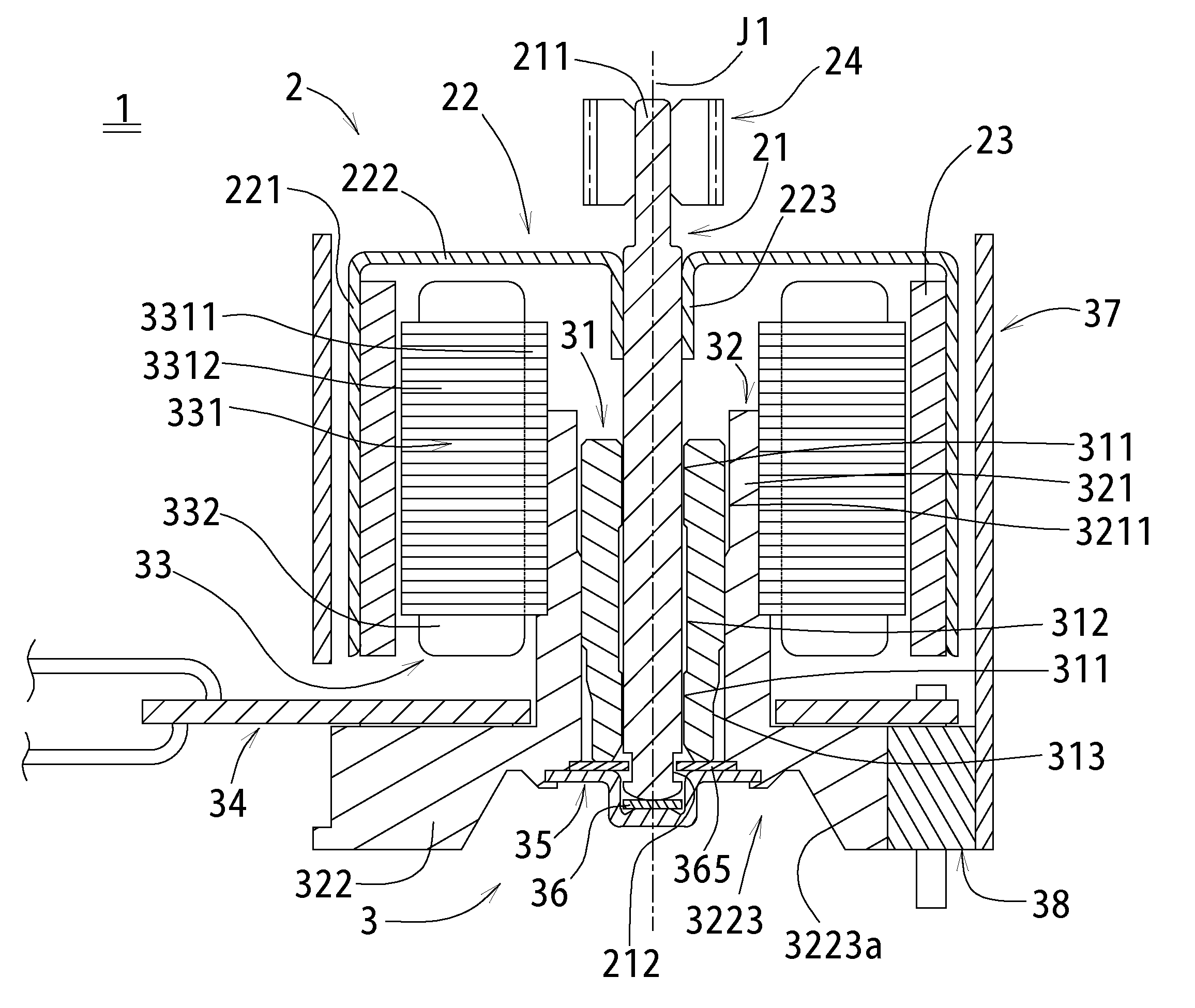
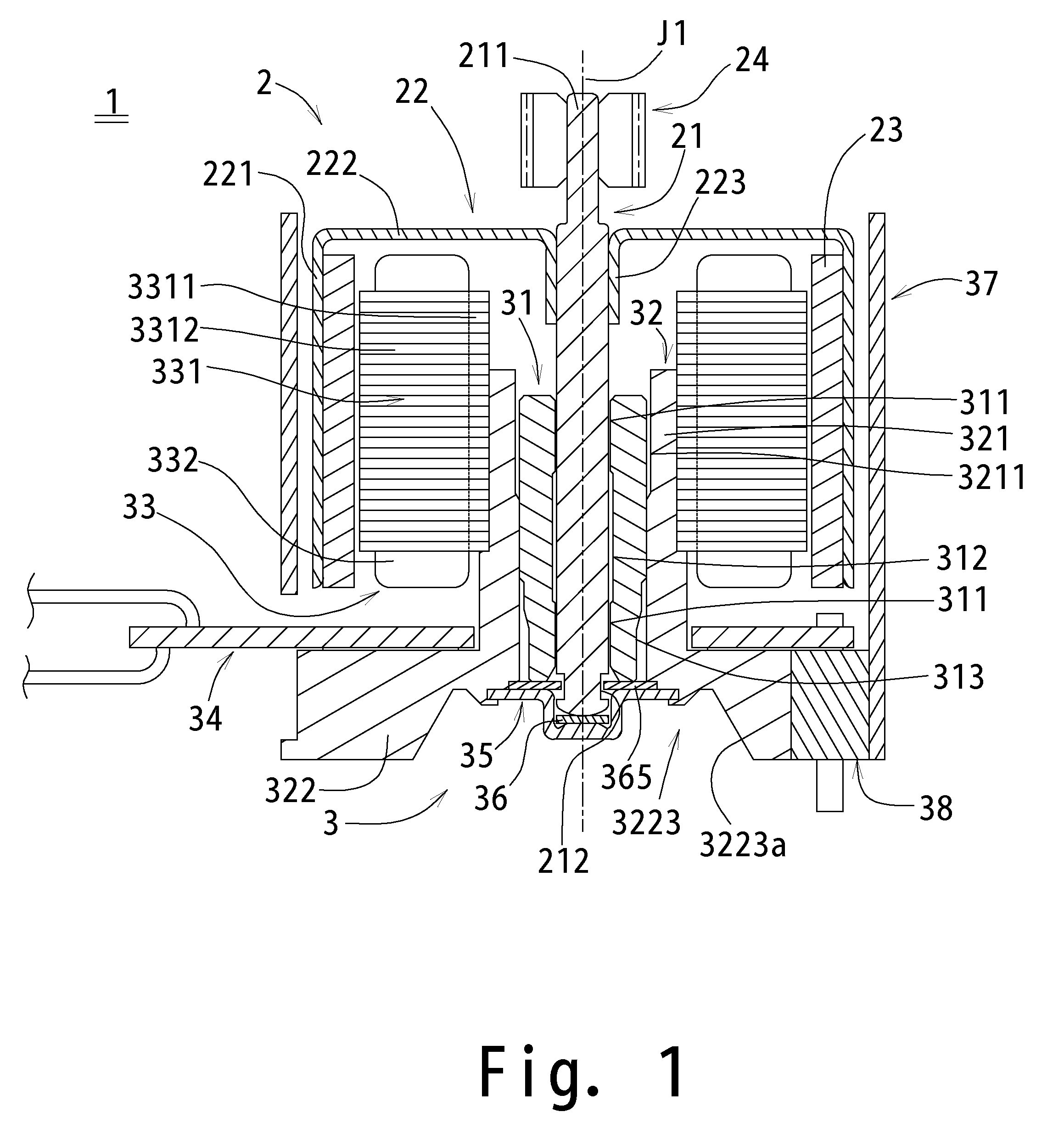
[0019]Referring to FIGS. 1 through 8, preferred embodiments of the present invention will be described in detail. It should be noted that in the explanation of the preferred embodiments of the present invention, when positional relationships among and orientations of the different components are described as being up / down or left / right, ultimately positional relationships and orientations that are in the drawings are indicated. Positional relationships among and orientations of the components once having been assembled into an actual device are not indicated. Additionally, in the following description, an axial direction indicates a direction substantially parallel to a rotation axis, and a radial direction indicates a direction substantially perpendicular to the rotation axis.

[0020]Description is given below to an entire configuration of a brushless motor according to a preferred embodiment of the present invention with reference to FIG. 1. FIG. 1 is a cross-sectional view, cut alo...


PUM


Abstract

A servo unit is arranged to operate an actuator, and a brushless motor is utilized in the servo unit. The brushless motor includes a rotational portion provided with a shaft and a rotor magnet rotating integrally with the shaft, a bearing portion rotatably supporting the shaft, a housing provided with a cylindrical portion retaining the bearing portion and a base portion bulging radially outwards from an axially lower portion of the cylindrical portion, a stator provided with a stator core having an inner peripheral surface to radially oppose an outer peripheral surface of the cylindrical portion of the housing and coils formed by conductive wires wound around the stator core, and a motor circuit board disposed on an axially upper side of the base portion. The base portion of the housing is arranged on an outer peripheral surface with a substantially arcuate concave portion which is concave in a radially inward direction. The substantially arcuate concave portion contains a pin holder which is made of an electrically insulating material to hold a plurality of metal pins. The respective pins are electrically connected to the motor circuit board.

Description

BACKGROUND OF THE INVENTION[0001]1. Field of the Invention[0002]The present invention relates to a servo unit used to operate an actuator, and a brushless motor provided in the servo unit.[0003]2. Description of the Related Art[0004]An actuator controlled remotely or automatically has been conventionally utilized to operate a joint of an artificial robot or the like. Combinations of a plurality of servo units in series can be used to realize various operations of the joint of the artificial robot. In many cases, each of the servo units of this type is mounted with a brush motor or a coreless motor as a drive source.[0005]A brush motor or a coreless motor mounted in a servo unit is required to rotate at a high rotation speed of at least 20,000 rotations per minute in order to generate enough rotary torque for an output shaft of the servo unit. Thus, there arises a problem of a large amount of noise generated by the high speed rotation of the brush motor or the coreless motor. There i...

Claims


Application Information

Patent Timeline
IPC IPC(8): H02K3/18H02K7/116
CPCH02K1/187H02K5/1675H02K7/116H05K3/3447H02K11/0073H02K2203/03H05K3/3405H02K11/0021H02K11/215H02K11/33
Inventor KANATANI, TADAYUKIONO, KAZUHIROSAKAI, TEPPEI
Owner MURATA MASCH LTD
Why Eureka
Try Eureka