Video/Audio Processing Device and Apparatus Connected to the Same

a processing device and video/audio technology, applied in the field of video/audio processing devices, can solve the problems of increasing power consumption, increasing power consumption, and increasing the processing contents of the system, and achieve the effect of reducing power consumption during standby

Active Publication Date: 2009-02-12
PANASONIC CORP
View PDF13 Cites 44 Cited by
  • Summary
  • Abstract
  • Description
  • Claims
  • Application Information

AI Technical Summary

Benefits of technology

[0012]According to the present invention, as the standby mode in the power “off” state, aside from the first standby mode (operation mode that maintains the video / audio processing device in the normal power “off” state), the second standby mode having power consumption larger than that of the first standby mode (operation mode that maintains the video / audio processing device in the “apparent power-off” state) is prepared. The first and second standby modes are switched in conjunction with the external equipment. Power consumption during standby can be reduced.

Problems solved by technology

It has been recently accelerated to make the DVD recorders multifunctional, increasing power consumption thereof.
Processing contents of a system have been required to be as complicated as those of a personal computer, and power consumption tends to be increased.

Method used


Image

  • Video/Audio Processing Device and Apparatus Connected to the Same
  • Video/Audio Processing Device and Apparatus Connected to the Same
  • Video/Audio Processing Device and Apparatus Connected to the Same

Examples


embodiment 1

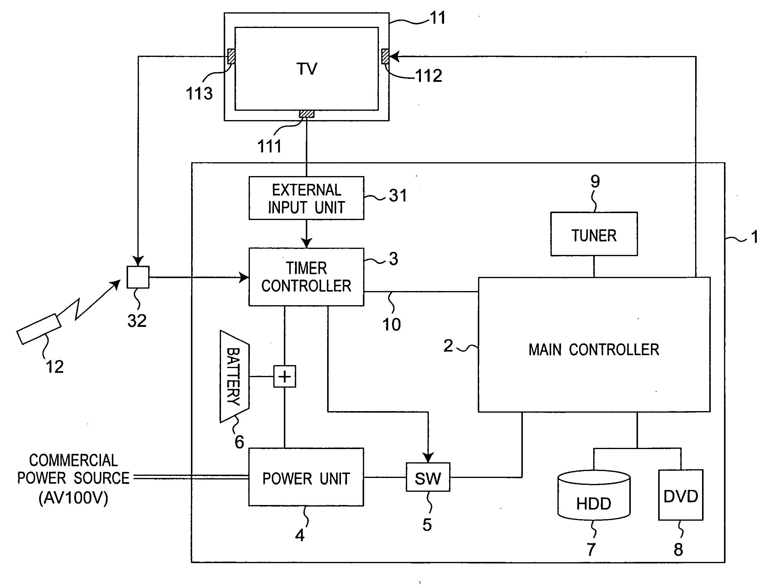
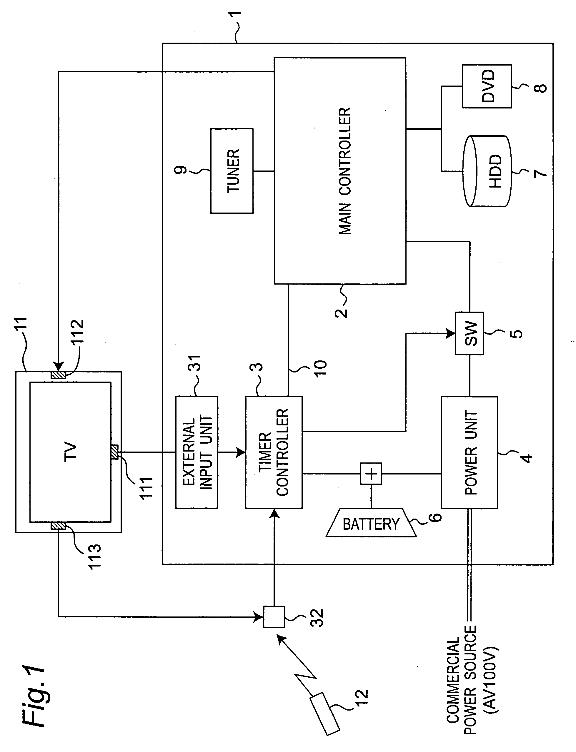
[0053]Embodiment 1 of the present invention is described below. In the following description, a television, for example, is used for an external equipment. FIG. 1 is a block diagram of the entire system, focusing on a power control system of the recording / reproducing apparatus of Embodiment 1 of the present invention.

1. System Configuration

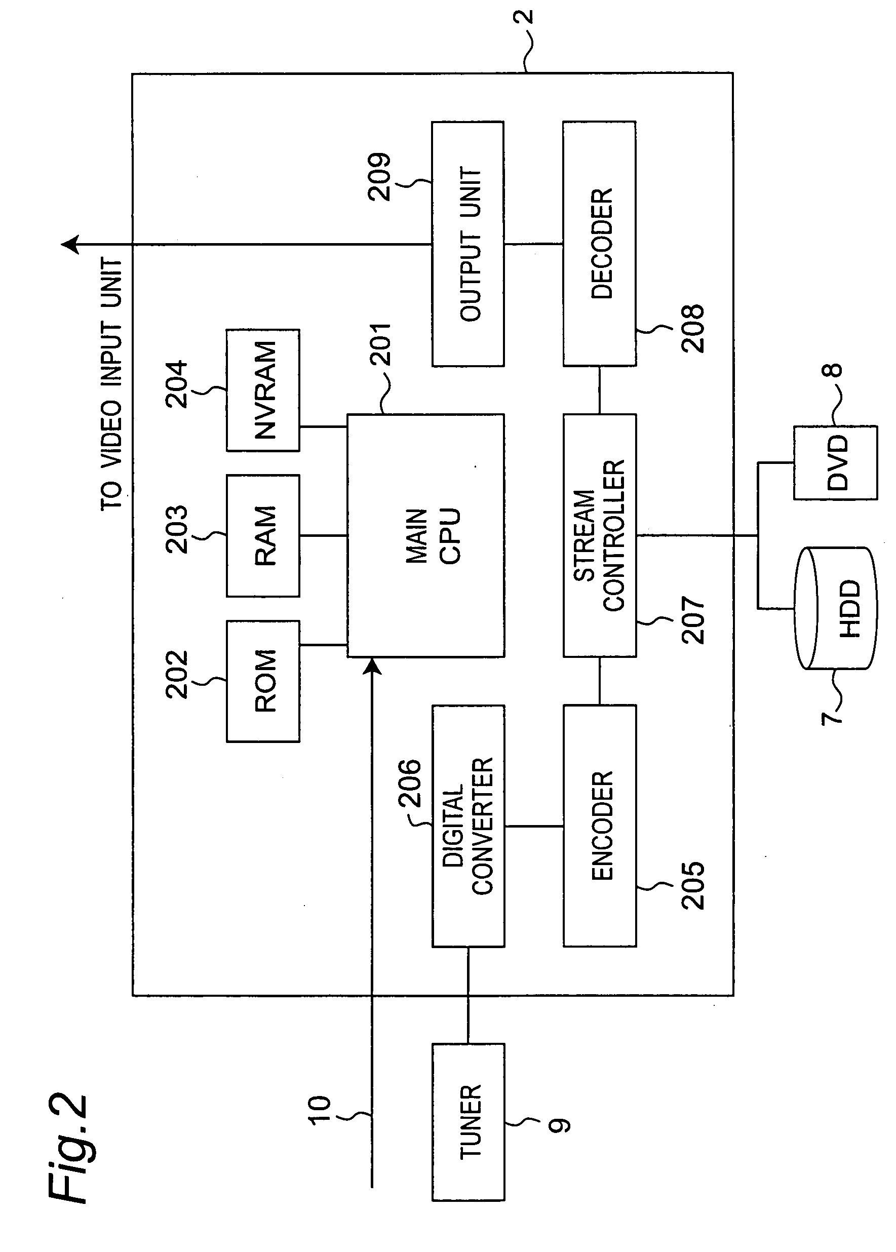
[0054]A main controller 2 in a recording / reproducing apparatus 1 performs main processing as a device for recording / reproducing, such as recording and reproducing processing in the recording / reproducing apparatus 1. A timer controller 3 performs clock-processing for power control to the main controller 2, reception of a remote controller signal, and programmed recording. An external input unit 31 is means for inputting an external video or audio signal to the timer controller 3. An IR input unit 32 inputs an infrared signal (“IR signal”) of the remote controller to the timer controller 3.

[0055]A power unit 4 supplies direct-current power from comm...

embodiment 2

[0116]Embodiment 2 of the present invention is described with reference to FIG. 11. The recording / reproducing apparatus 1 shown in FIG. 11 has a net interface unit 13 in addition to the configuration shown in FIG. 1. As in the timer controller 3, power is supplied from the power unit 4 and the battery 6 to the net interface unit 13. In particular, when the power unit 4 is in power-failure, the power is supplied from the battery 6. The net interface unit 13 is connected to the communication unit 10 and can communicate with the timer controller 3 and the main controller 2.

[0117]The television 11 has a net connection unit 114 connected to the net interface unit 13. The net connection unit 114 can communicate with the net interface unit 13. Communication processing between the television 11 and the recording / reproducing apparatus 1 is enabled. Other configuration is the same as the configuration in FIG. 1 of Embodiment 1.

[0118]The television 11 transmits, to the net interface unit 13 of...

embodiment 3

[0128]Embodiment 3 of the present invention is described with reference to FIG. 12. The recording / reproducing apparatus 1 shown in FIG. 12 has an illumination detector 33 connected to the timer controller 3 in place of the external input unit 31 of the configuration shown in FIG. 1. The illumination detector 33 has an illumination sensor for detecting an illumination.

[0129]FIG. 12 shows a lighting equipment 14 with the recording / reproducing apparatus 1. The lighting equipment 14 is attached as a lighting device in a room in which the recording / reproducing apparatus 1 is installed. Typically, the power of the lighting equipment 14 is turned “on” when a person enters the room to use it and is turned “off” when the person exits the room.

[0130]The illumination detector 33 of the recording / reproducing apparatus 1 can detect and determine “on” or “off” of the power of the illumination equipment 14. “On” or “off” of the power of the illumination equipment 14 is replaced with “on” or “off” ...


PUM

PropertyMeasurementUnit
power consumptionaaaaaaaaaa

Abstract

A video / audio processing device (1), such as a DVD recorder, has controller (2) for controlling a state of power-on / off. The controller (2) has a first standby mode and a second standby mode having power consumption larger than that of the first standby mode in a power-off state of the video / audio processing device (1). The first standby mode is a mode for maintaining a power of the video / audio processing device (1) in the “off” state. The second standby mode is a mode for maintaining the power of the video / audio processing device (1) in an apparent “off” state. The controller (2) switches between the first standby mode and the second standby mode in conjunction with a state of power-on / off of external equipment (11) such as television.

Description

TECHNICAL FIELD[0001]The present invention relates to a video / audio processing device, such as a hard disk recorder and a DVD recorder, having a function of programmed-recording for television broadcast.BACKGROUND ART[0002]In recent years, widespread use of household electrical appliances equipped with digital technique has been remarkable. In particular, DVD (Digital Versatile Disc) recorders with hard discs have been rapidly widespread and the number of manufacturers newly entering into the market has been increasing. It has been recently accelerated to make the DVD recorders multifunctional, increasing power consumption thereof. Processing contents of a system have been required to be as complicated as those of a personal computer, and power consumption tends to be increased. Such household electrical appliances have also been required to give consideration to the Earth environment. Necessity for reducing power consumed by the appliances becomes higher.[0003]An example of a conve...

Claims


Application Information

Patent Timeline
Patent Type & Authority Applications(United States)
IPC IPC(8): H04N5/00G11B19/00G11B31/00H04N1/00H04N5/76
CPCG11B19/02G11B31/00H04N5/775H04N7/163G06F1/3203H04N21/4147H04N21/42646H04N21/4432H04N21/4122H04N5/63H04N5/76H04N5/765
Inventor KUNO, YOSHIKI
Owner PANASONIC CORP
Why Eureka
Try Eureka