
Method and apparatus to provide bonded optical network devices

a technology of optical network devices and optical network devices, applied in the direction of electrical devices, multiplex communication, transmission, etc., can solve the problems of increasing customer demand for ont port combinations that are not currently supported, limited throughput, and high development and support costs

Inactive Publication Date: 2009-02-12
TELLABS VIENNA
View PDF10 Cites 22 Cited by
  • Summary
  • Abstract
  • Description
  • Claims
  • Application Information

AI Technical Summary

Problems solved by technology

There are traditional networking products that provide limited throughput due to hardware limitations.
However, that would be expensive to develop and support.
Further, customer demands for ONT port combinations that are not currently supported continue to grow.
Market demand is unclear and variable; therefore the market is unlikely to devote a significant amount of resources to development costs for ONTs.

Method used


Image

  • Method and apparatus to provide bonded optical network devices
  • Method and apparatus to provide bonded optical network devices
  • Method and apparatus to provide bonded optical network devices

Examples


Embodiment Construction

[0023]A description of example embodiments of the invention follows.

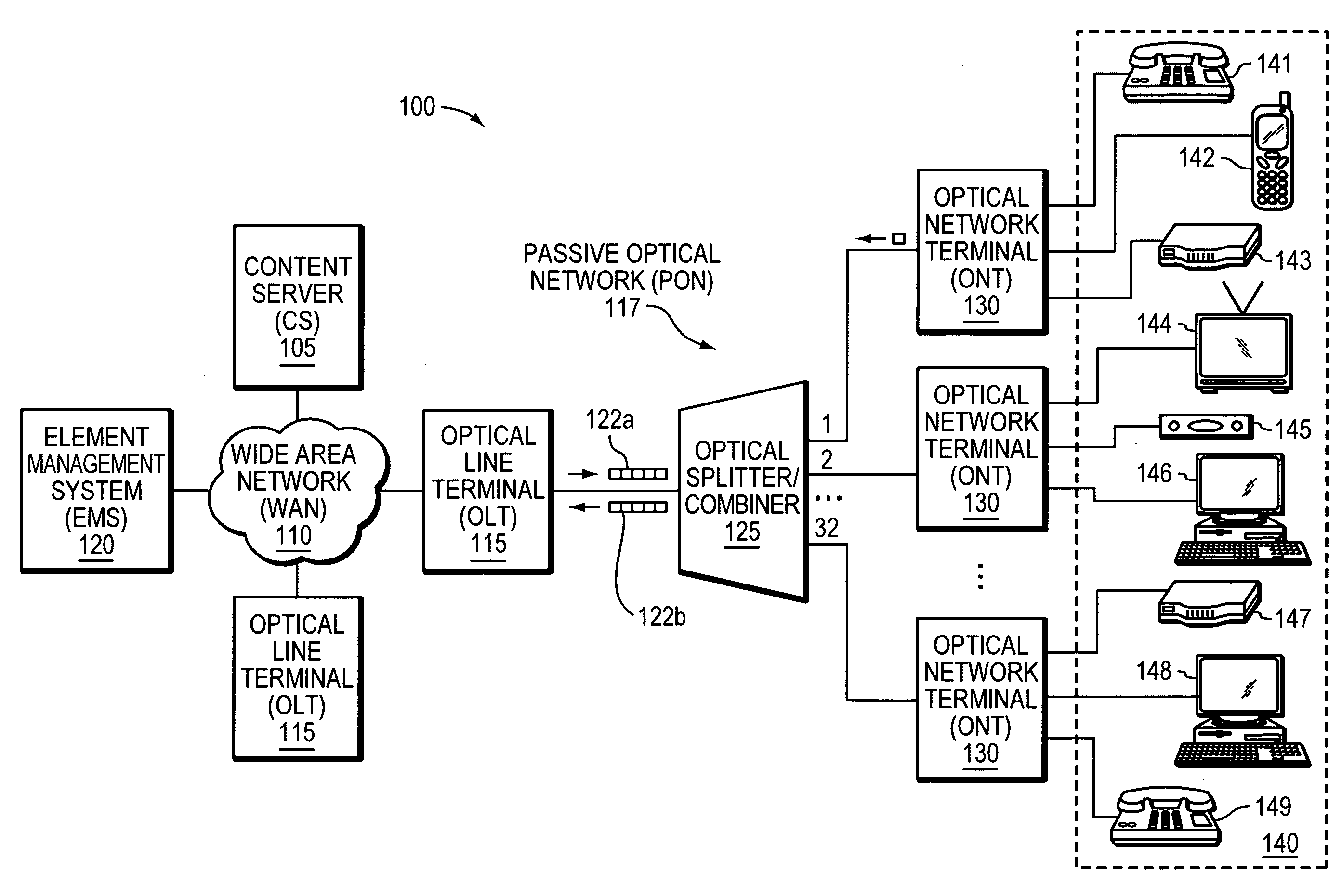
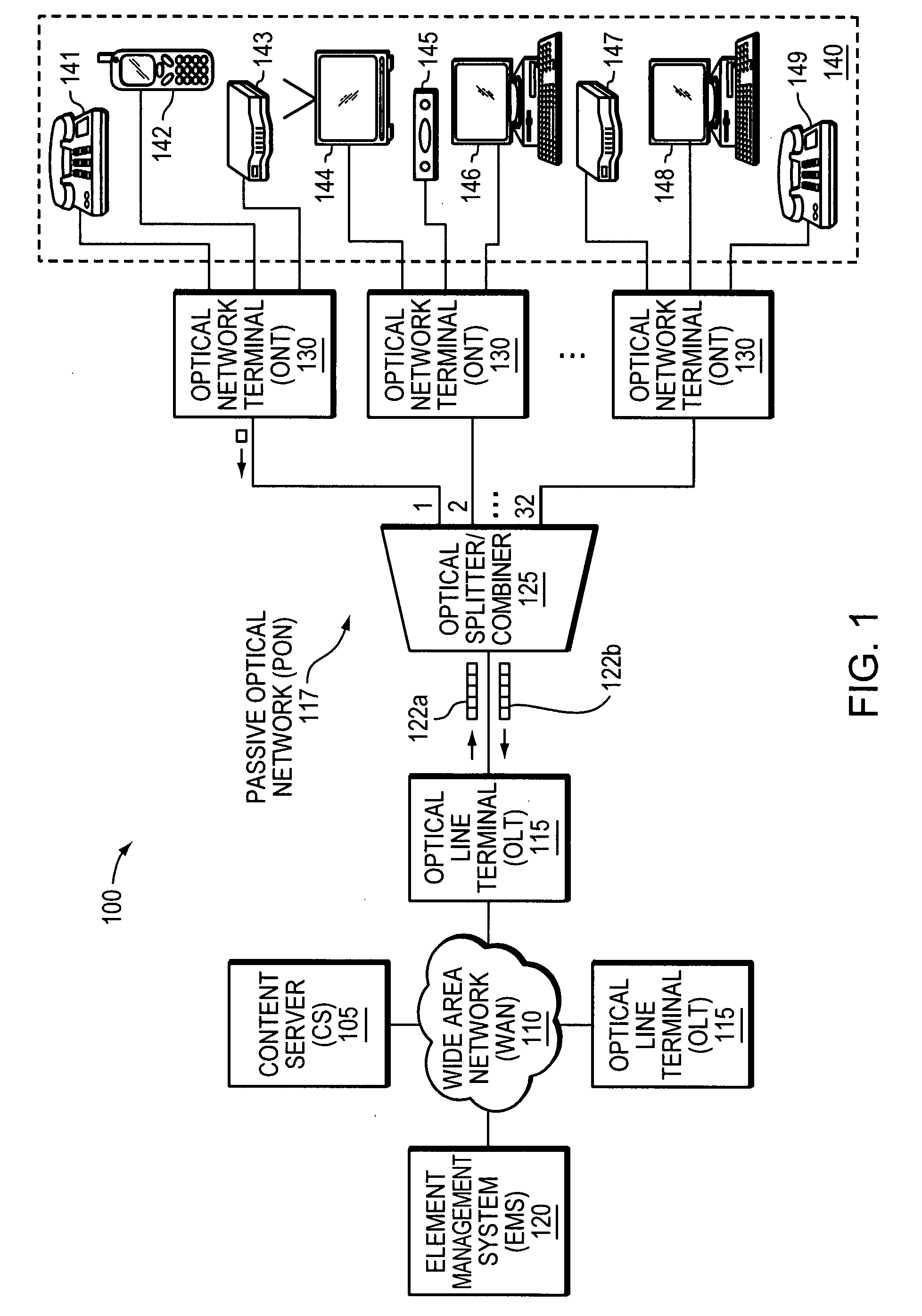
[0024]FIG. 1 is a block diagram of an example network 100 in which example embodiments of the present invention may be employed. The network 100 includes a Wide Area Network (WAN) 110 and a Passive Optical Network (PON) 117. The WAN 110 may be a network such as the Internet, and the PON 117 is typically a more localized network in which optical signals, used to transmit information, traverse passive optical elements, such as splitters and combiners, to be communicated between network nodes.

[0025]The example network 100 of FIG. 1 includes one or more Optical Line Terminals (OLTs) 115, an Element Management System (EMS) 120, and a Content Server (CS) 105, all connected, generally, by the WAN 110. In the example network 100, each OLT 115 transmits / receives information in the form of a frame of packets 122a, 122b embodied on optical signals to / from an optical splitter / combiner (OSC) 125 to communicate with, for example,...


PUM


Abstract

An apparatus and corresponding method for a bonded Optical Network Terminals (ONT) enhances throughput, redundancy and user-port flexibility by Passive Optical Network (PON) services, such as Gigabit-capable (GPON), Broadband PON (BPON), Ethernet PON (EPON) and future PON services, by mechanically or logically externally managing a plurality of individual ONTs as a single bonded ONT while maintaining individual internal management. Further, multiple OLTs may communicate with the same ONT, thereby increasing throughput and providing redundancy. For manufacturers, user-port flexibility reduces time-to-market for unique products to meet specific user needs. That is, different applications may require multiple ONTs to be managed as a single device, yet provide the port counts from various ONTs. For service providers, mechanical or logical combination(s) of ONTs allows management from a user perspective, providing an opportunity for servicing a single device, improving accounting, billing, inventory, etc.

Description

BACKGROUND OF THE INVENTION[0001]There are traditional networking products that provide limited throughput due to hardware limitations. For example, some Optical Network Terminal (ONT) System on Chip (SoC) products provide one Gigabit Media Independent Interface (GMII) interface, which provides up to 1 Gigabit per second (Gbps) of user capacity to an on-board Ethernet Switch or Network processor that contains several user data ports. There are applications where it is useful for multiple User-to-Network Interface (UNI)-side GMII interfaces to provide greater than 1 Gbps of total user throughput capacity. This requirement applies more to ONTs with several users connected, such as in a business or a multi-dwelling environment. One approach is to create an SoC that provides additional throughput via multiple GMII interfaces. However, that would be expensive to develop and support. Other approaches include multiplexing the individual streams into one stream and then demultiplexing the s...

Claims


Application Information

Patent Timeline
IPC IPC(8): H04J14/00
CPCH04L41/0893H04Q2011/0079H04Q2011/0075H04Q11/0067
Inventor BERNARD, MARC R.ROESCH, JOSEPH C.ATKINSON, DOUGLAS A.
Owner TELLABS VIENNA
Learn More