Intraocular lens insertion device

Active Publication Date: 2009-02-12
HOYA CORP
View PDF101 Cites 82 Cited by
  • Summary
  • Abstract
  • Description
  • Claims
  • Application Information

AI Technical Summary

Benefits of technology

[0014]In addition, the intraocular lens insertion device according to the third aspect can prevent the contact surface of the upper holding member from contacting the optical area of the lens and can hold the lens without deforming the curved optical area, due to the curved shape of the contact surface viewed from the side.
[0015]In addition, the intraocular lens insertion device according to the fourth aspect is provided with an upper holding member formed with an insertion pass-through groove having a width nearly the same or larger than the outside shape of the lens discharge mechanism such tha

Problems solved by technology

However, a characteristic of the invention disclosed in the above-mentioned JP '570 and JP '572 is that during use the lens must be moved from the holding position to a position from where it can be discharged, and there is concern that problems will occur during the moving operation.
In addition, the construction is such that after mov

Method used


Image

  • Intraocular lens insertion device
  • Intraocular lens insertion device
  • Intraocular lens insertion device

Examples


Embodiment Construction

[0023]The following describes preferred embodiments of the present invention with reference to the drawings.

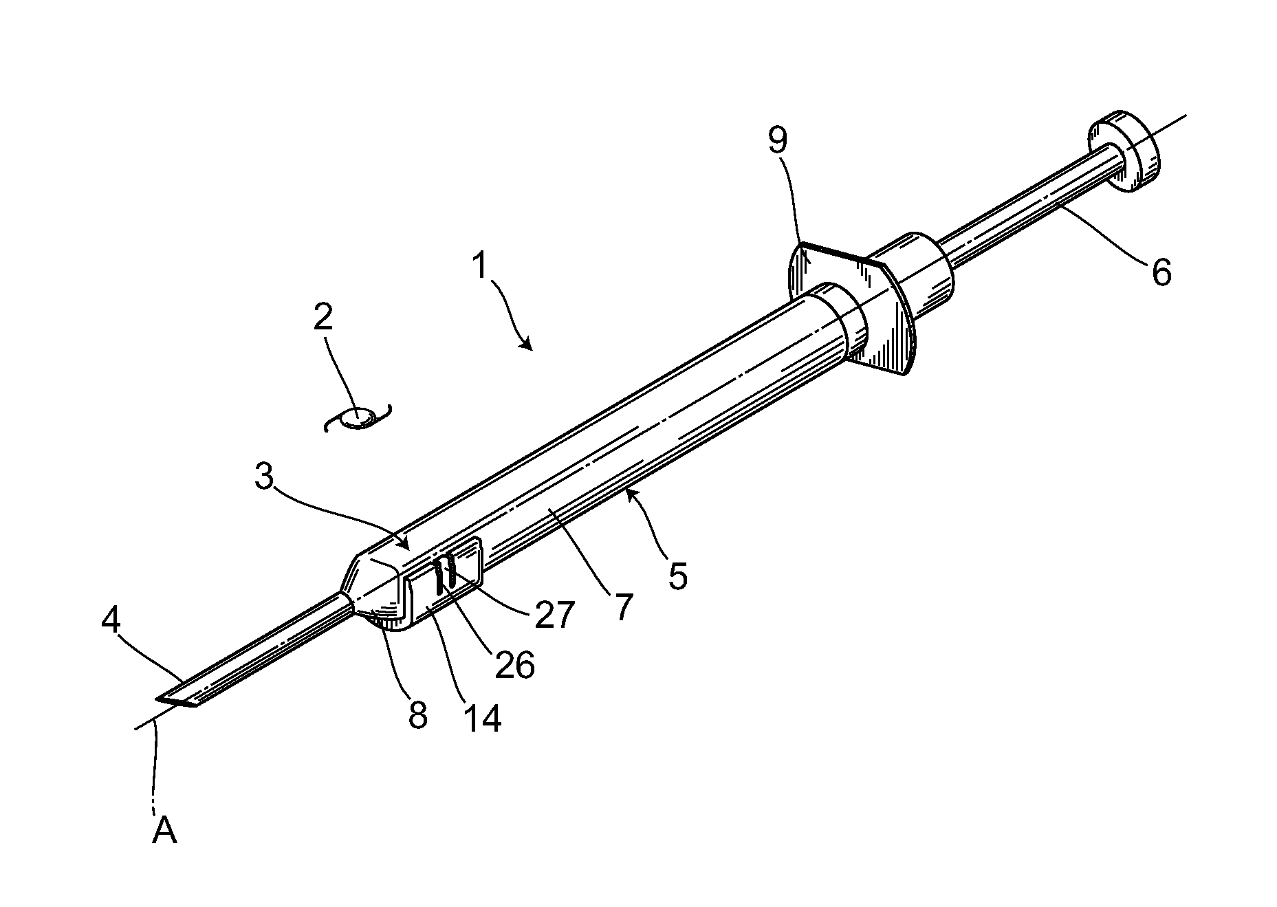
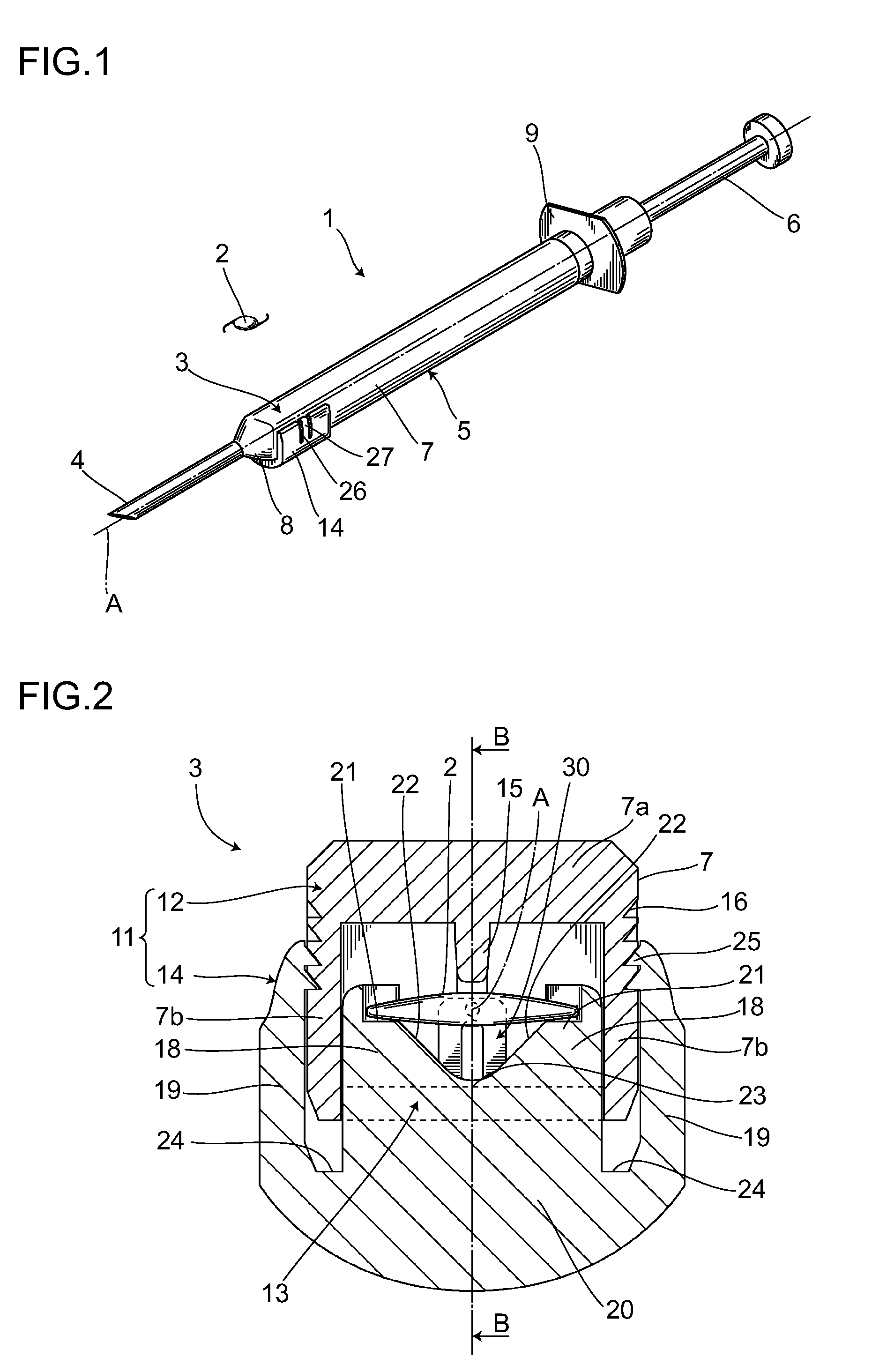
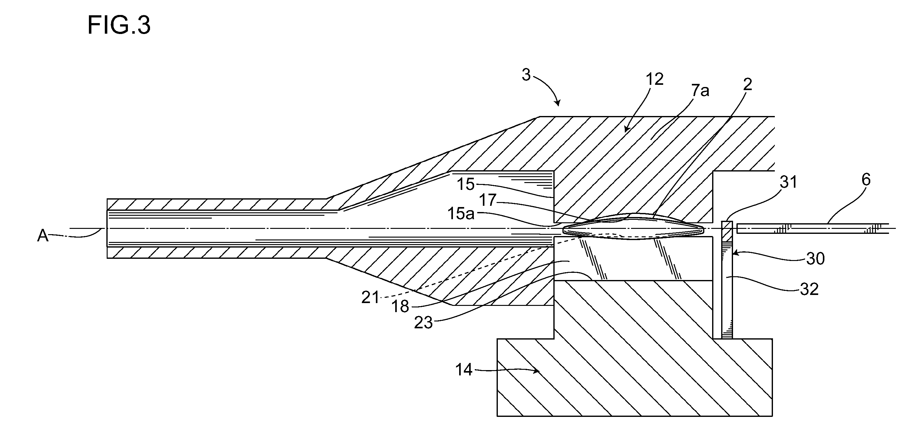
[0024]The intraocular lens insertion device 1 shown in FIG. 1 is used to safely and quickly discharge into an eye a deformable intraocular lens 2 (hereinafter referred to as “lens 2”), and more particularly is a preset type intraocular lens insertion device 1 having a lens 2 preset in the intraocular lens insertion device 1. More specifically, the intraocular lens insertion device 1 is provided with a body 5 having a lens placement section 3 that holds the lens 2 and a tube section 4 that inserts the lens 2 into an eye, and a plunger 6 serving as a lens discharge mechanism that discharges the lens 2 that is placed in the afore-mentioned lens placement section 3.

[0025]The lens 2 used here may be made of a soft material, such as silicone resin, acrylic resin, or hydrogel.

[0026]The afore-mentioned body 5 is constructed of a tubular material and comprises the afore-mentioned tube ...


PUM


Abstract

An intraocular insertion device capable of safely performing discharge operation of a lens by a simpler construction. The intraocular lens insertion device has a body provided with a lens placement section where the lens is placed and a tube section for inserting the lens into an eye and has a plunger for discharging the lens placed on the lens placement section. The lens placement section has an upper holding member and a lower holding member. The upper holding member has a rib projecting on advancement axis A, to the lower side of the lens placement section. The lower holding member has a U-shaped cross-section and is constituted of a left and right pair of uprising sections and a pressing section uniting the uprising sections at their lower ends.

Description

CROSS REFERENCE TO RELATED APPLICATIONS[0001]This is a U.S. national phase application under 35 U.S.C. § 371 of International Patent Application No. PCT / JP2006 / 300217 filed Jan. 11, 2006, which claims priority to Japanese patent application No. 2005-018850, filed Jan. 26, 2005. The International Application was published in Japanese on Aug.3, 2006 as International Publication No. WO 2006 / 080191 A1 under PCT Article 21(2). The content of both applications is incorporated herein in its entirety.FIELD OF THE INVENTION[0002]The present invention relates to an intraocular lens insertion device that inserts an intraocular lens into an aphakic eye after a cataract operation, or, to an intraocular lens insertion device that inserts a phakic intraocular lens during a refractive surgery.DESCRIPTION OF THE RELATED ART[0003]In cataract operations, the method of removing an opacified lens by phacoemulsification (PEA) and implanting an intraocular lens after the opacified lens has been removed is...

Claims


Application Information

Patent Timeline
IPC IPC(8): A61F9/007
CPCA61F2/1678A61F2/1691
Inventor ICHINOHE, TAKASHIKUDOH, KAZUNORI
Owner HOYA CORP
Why Eureka
Try Eureka