Worksite zone mapping and collision avoidance system

a worksite and collision avoidance technology, applied in the field of machine control systems, can solve the problems of insufficient warning for the operator to adequately maneuver the machine, low accuracy, and inability to accurately detect the movement of the machine, and achieve the effect of avoiding collisions of the mobile machine with other objects

Inactive Publication Date: 2009-02-12
CATERPILLAR INC
View PDF21 Cites 137 Cited by
  • Summary
  • Abstract
  • Description
  • Claims
  • Application Information

AI Technical Summary

Benefits of technology

[0010]And yet another aspect of the present disclosure is directed to a method of avoiding collisions of a mobile machine with other objects at a common worksite. The method includes receiving a map of the worksite, the map having an electronic representation of an object at the worksite and at least one boundary zone positioned around the object. The method also includes initiating a collision avoidance strategy in response to a mobile machine entering the at least one boundary zone.

Problems solved by technology

At these worksites, because of the size of these machines, lack of visibility, slow response time, and difficulty of operation, operators must be keenly aware of their surroundings.
In some situations, there may be insufficient warning for the operator to adequately maneuver the machine away from damaging encounters.
Although the sensing system of the '856 publication may help minimize the likelihood of damaging encounters by sensing obstacles in a zone about a moving vehicle and warning an operator or autonomously slowing the vehicle based on near obstacles, it may be expensive and limited.
That is, because every vehicle is required to have a sensing system, the cost of each vehicle may increase substantially.
For fleet operations, this increased cost may be prohibitive.
Further, because the sensing system of the '856 publication only takes into account characteristics of the vehicle, the protection provided by the system may be inadequate for some obstacles or other mobile machines in the path of the vehicle.

Method used


Image

  • Worksite zone mapping and collision avoidance system
  • Worksite zone mapping and collision avoidance system
  • Worksite zone mapping and collision avoidance system

Examples


Embodiment Construction

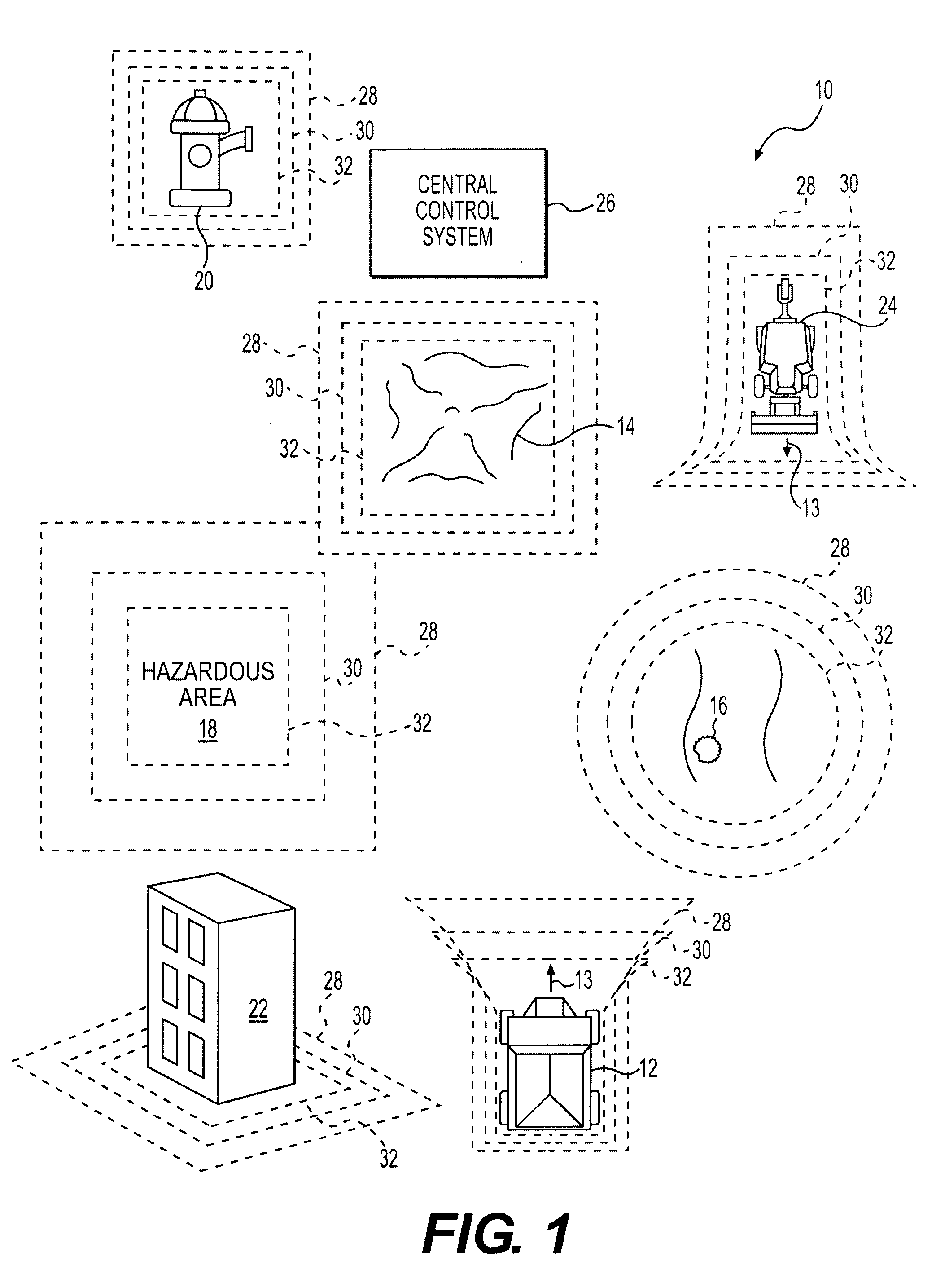
[0014]FIG. 1 illustrates an exemplary worksite 10 with a mobile machine 12 performing a predetermined task. Worksite 10 may include, for example, a mine site, a landfill, a quarry, a construction site, a road worksite, or any other type of worksite. The predetermined task may be associated with any work activity appropriate at worksite 10, and may require machine 12 to generally traverse worksite 10.

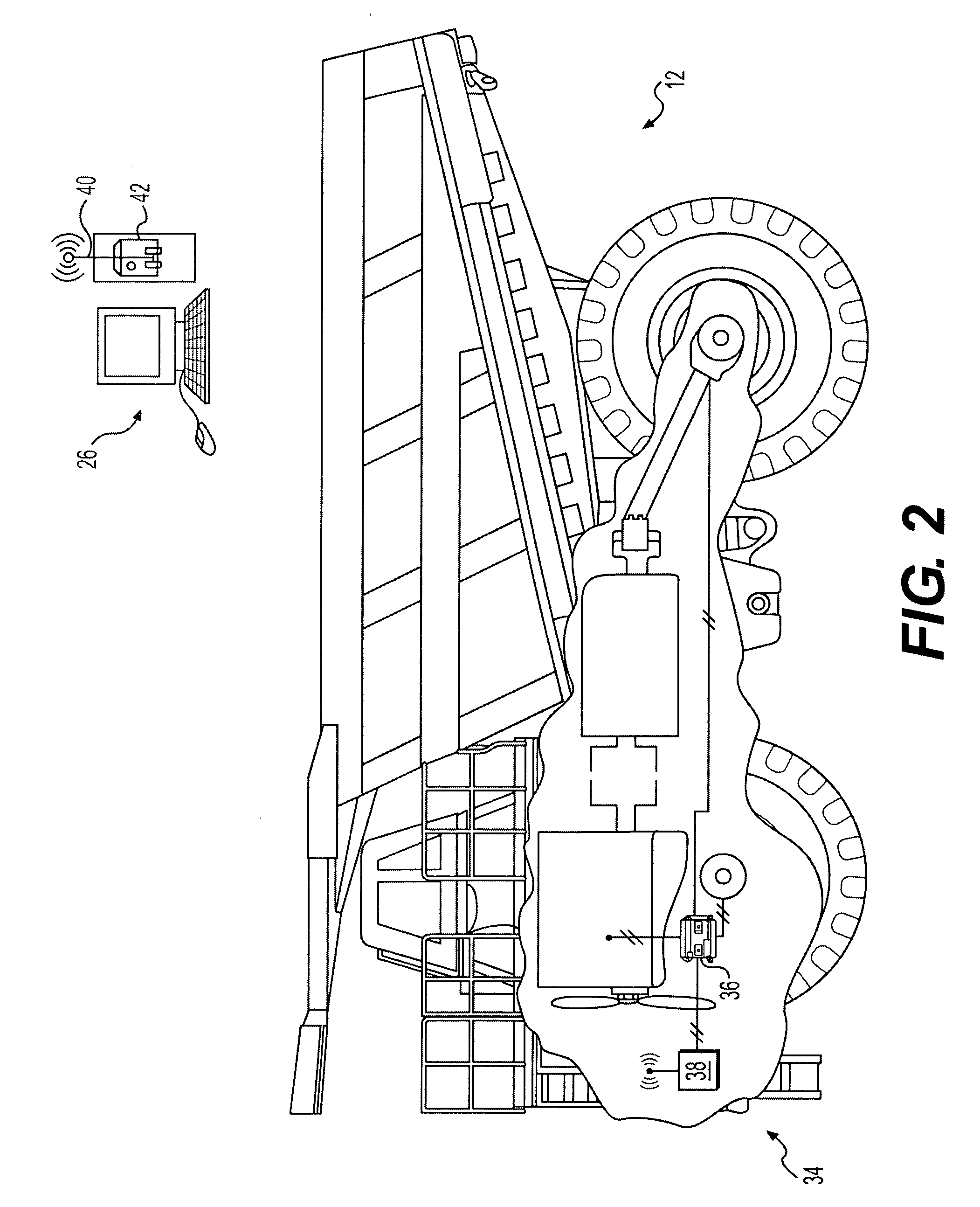
[0015]Machine 12 may embody any type of driven machine that may be used at worksite 10. For example, machine 12 may embody a haul truck, an excavator, a motor grader, a backhoe, or a water truck. Machine 12 may generally be moved about worksite 10 by a power source such as a motor or an engine. Machine 12 may have a direction represented in FIG. 1 by an arrow 13, a velocity represented by a length of arrow 13, and an acceleration (not represented). Although not shown, the movement of machine 12 may be at least partially determined by an acceleration control, a braking control, and a dire...


PUM


Abstract

A worksite mapping system is disclosed. The worksite mapping system has a receiving module configured to receive a position and a characteristic of an object at a worksite, a positioning device configured to determine a position of a mobile machine at the worksite, and a controller in communication with the receiving module and the positioning device. The controller is configured to generate an electronic map of the worksite, and an electronic representation of the object on the electronic map based on the received position. The controller is further configured to generate at least one boundary zone around the object based on the received characteristic, and an electronic representation of the mobile machine on the electronic map based on the determined position. The controller is further configured to initiate a collision avoidance strategy in response to a mobile machine entering the at least one boundary zone.

Description

[0001]This application claims the benefit of U.S. Provisional Application No. 60 / 929,503, filed Jun. 29, 2007, and U.S. Provisional Application No. 60 / 929,504, filed Jun. 29, 2007.TECHNICAL FIELD[0002]The present disclosure is directed to a machine control system, including a worksite mapping system, and more particularly, to a system for mapping zones about stationary objects and mobile machines at a worksite to control mobile machines to avoid collisions with stationary objects and other mobile machines at a common worksite.BACKGROUND[0003]Mobile machines such as, for example, haul trucks, excavators, motor graders, backhoes, water trucks, and other large equipment are utilized at a common worksite to accomplish a variety of tasks. At these worksites, because of the size of these machines, lack of visibility, slow response time, and difficulty of operation, operators must be keenly aware of their surroundings. Specifically, each operator must be aware of the location of stationary...

Claims


Application Information

Patent Timeline
Patent Type & Authority Applications(United States)
IPC IPC(8): G08G1/16G06F19/00
CPCB60W30/08E02F9/26E02F9/2033B60W50/14
Inventor STRATTON, KENNETH LEEDARBY, G. DERRICKSHULTS, JAMIEBRIGGS, ROBERTOPDENBOSCH, AUGUSTOSANTAMARIA, JUAN CARLOSYUET, FU PEICLAR, JEAN-JACQUES
Owner CATERPILLAR INC
Why Eureka
Try Eureka