
Electrostatic lubricant dispensing system

a technology of lubricant dispensing system and nozzle, which is applied in the direction of gearing details, machines/engines, lighting and heating apparatus, etc., can solve the problems of spraying or excessive application of lubricant, further waste and contamination of work area, and droplets not being effective for lubricating every pin

Active Publication Date: 2009-02-19
SPRAYING SYST
View PDF7 Cites 13 Cited by
  • Summary
  • Abstract
  • Description
  • Claims
  • Application Information

AI Technical Summary

Benefits of technology

[0004]It is an object of the present invention to provide a lubricant dispensing system adapted for specifically directing lubricant to critical areas without over spraying, misapplication, or contamination of the work environment.
[0005]Another object is to provide a lubricant dispensing system for roller / link chains which is adapted for directing precisely controlled small quantities of liquid to each pin and roller junction of the chain, even during high speed movement of the chain.
[0006]A further object is to provide a chain lubricant dispensing system as characterized above which is applicable for spraying each pin / roller connection without excessive waste from overspray, excessive application or fogging. A related object is to provide such a chain lubricant dispensing system which can be operated with oil savings of up to 95% as compared to conventional oil drip lubricators.

Problems solved by technology

Conventional lubricant application systems frequently result in over spraying or excessive application of lubricant to the target area in order to ensure coating of specific areas critical for lubrication.
Air atomized spraying also can create fogging that results in further waste and contamination of the work area.
Since the chains often are moved at high rates of speed, such as up to 400 fpm, however, the droplets are not effective for lubricating every pin.
Moreover, the lubrication that is dispensed in each droplet far exceeds the amount necessary for lubrication.
Hence, considerable waste results, as well as contamination to the surrounding work environment.

Method used


Image

  • Electrostatic lubricant dispensing system
  • Electrostatic lubricant dispensing system
  • Electrostatic lubricant dispensing system

Examples


Embodiment Construction

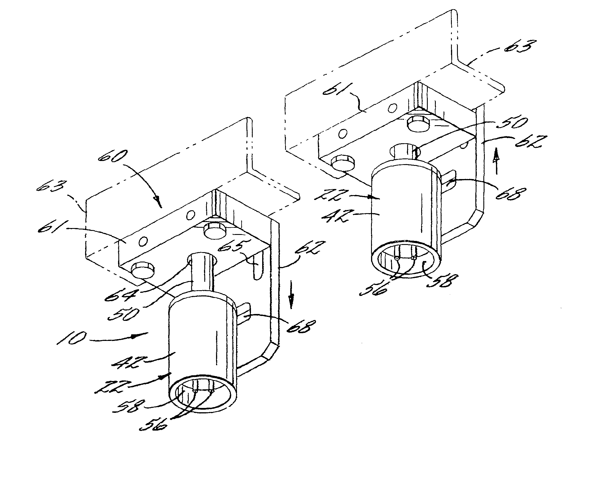
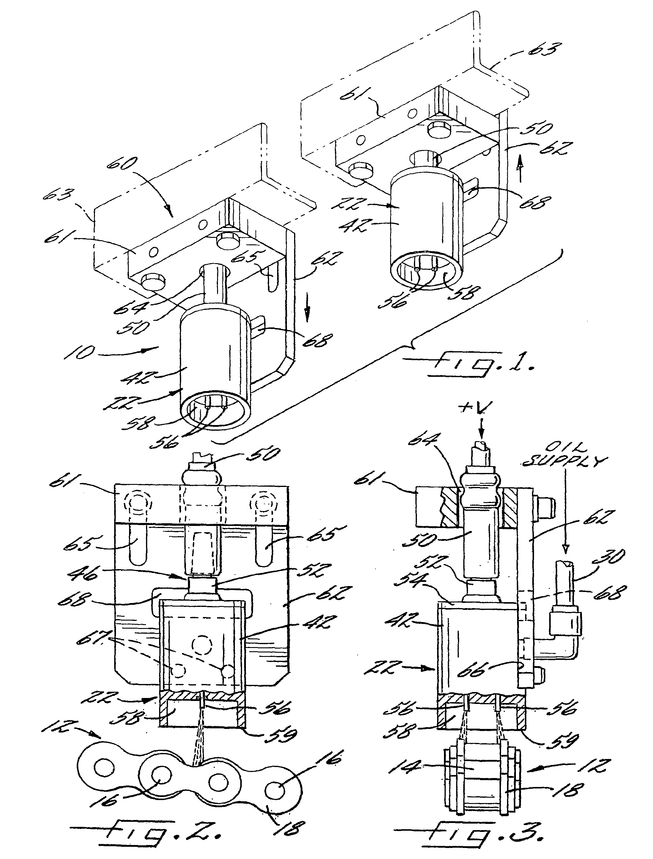
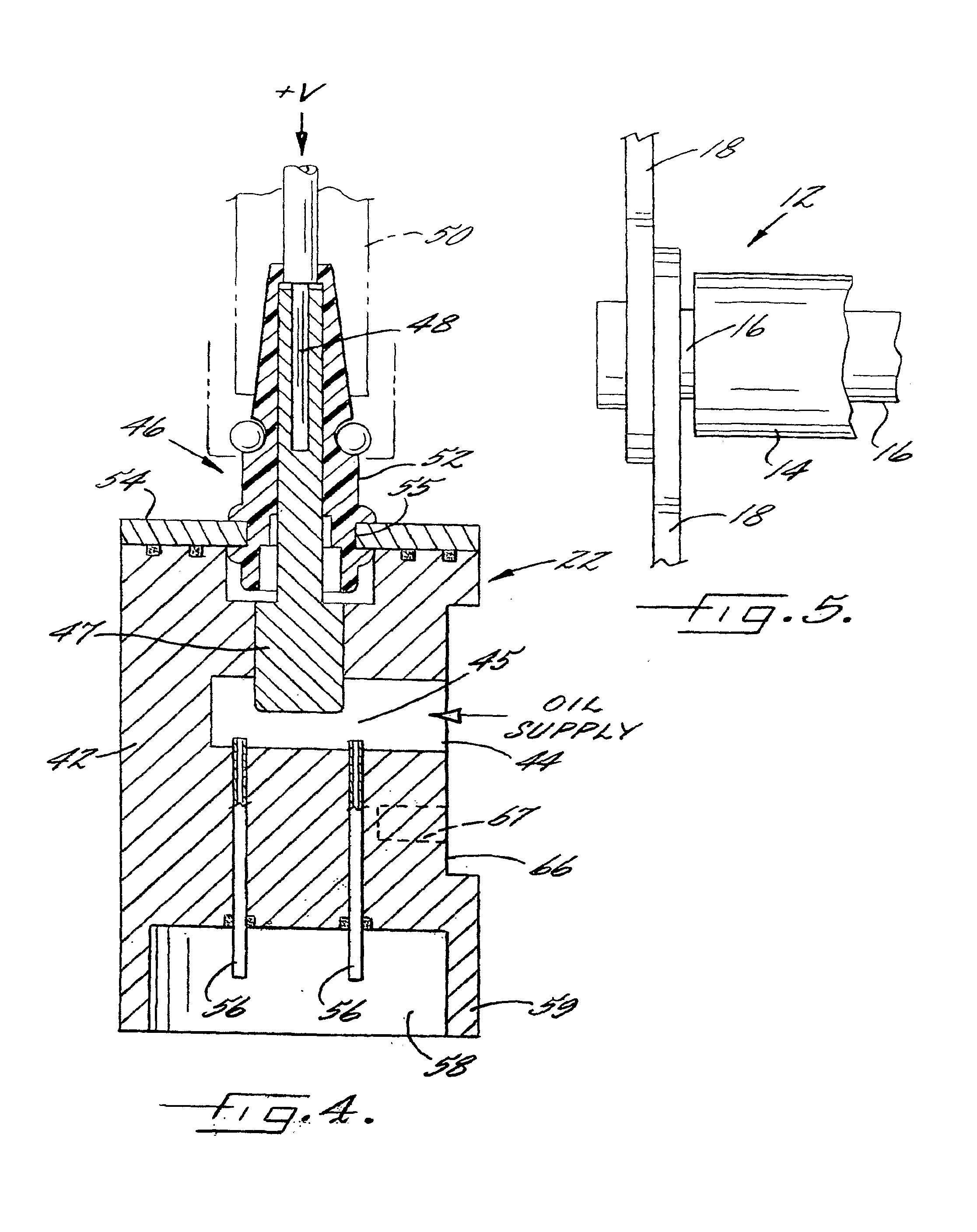
[0019]Referring now more particularly to FIG. 1 of the drawings, there is shown an illustrative lubricant dispensing system 10 in accordance with the invention. The illustrated lubricant dispensing 10 is designed for use in applying a lubricant such as oil to the pin and roller junctions of a sprocket driven chain 12 (see FIGS. 2 and 3). As shown in FIG. 5, such chains 12 typically comprise longitudinally spaced rollers 14 supported by respective pins 16, which in turn are connected by links 18 on opposed sides of the rollers 14. It is commonly necessary to lubricate the junctions between the pins 16 and rollers 14 to enhance operation and prevent wear. Because of space constraints heretofore this has been difficult. Drip lubricators have been used which utilize a pinch valve or the like to control dripping of lubricant onto the moving chain at locations adjacent ends of the pins. As indicated above, such lubricating systems have been ineffective for lubricating each pin, result in ...


PUM


Abstract

A lubricant dispensing system is provided. The dispensing system includes a lubricant supply, a lubricant dispensing nozzle and a control panel. The dispensing nozzle includes a nozzle body with a fluid passageway therein which is in fluid communication with the lubricant supply, an electrode assembly for electrostatically charging lubricant in the fluid passageway and at least one discharge orifice through which electrostatically charged lubricant can be discharged. The discharge orifice is defined by at least one spray needle having a first end in fluid communication with the fluid passageway and a second end that extends outward of the nozzle body. The control panel directs the flow of lubricant from the lubricant supply to the lubricant dispensing nozzle and controls the electric power supplied to the electrode assembly.

Description

CROSS-REFERENCE TO RELATED APPLICATIONS[0001]This patent application claims the benefit of U.S. Provisional Patent Application No. 60 / 764,525, filed Feb. 2, 2006.FIELD OF THE INVENTION[0002]The present invention relates to generally to spray nozzle assemblies, and more particularly spraying systems for directing lubricants onto metal parts.BACKGROUND OF THE INVENTION[0003]In many manufacturing operations, such as in connection with the manufacture or use of sprocket driven chains, metal stamping operations, or steel fabrication, it is necessary to direct lubricant onto specific areas of the metal parts. Conventional lubricant application systems frequently result in over spraying or excessive application of lubricant to the target area in order to ensure coating of specific areas critical for lubrication. Air atomized spraying also can create fogging that results in further waste and contamination of the work area. In the lubrication of sprocket driven chains, by way of example, it ...

Claims


Application Information

Patent Timeline
Patent Type & Authority Applications(United States)
IPC IPC(8): B05B5/025F23D11/32F16N7/24
CPCB05B1/14B05B5/035F16N7/34B05B15/067B05B5/0533B05B15/654F01M1/08F16H57/0456F16H57/05F16N2210/33
Inventor MULJONO, ERIC BUDI
Owner SPRAYING SYST
Learn More