System and Method for Premises Power Parameter and Power-Factor Reporting and Management

a technology of power parameter and power-factor, applied in the field of premises power, can solve the problems of inability to verify with real-world measurement, complex electrical power consumption measurement and distribution, and exacerbating the ability to generate accurate or even reasonable load models

Inactive Publication Date: 2009-02-19
OPTIMAL INNOVATIONS INC
View PDF17 Cites 28 Cited by
  • Summary
  • Abstract
  • Description
  • Claims
  • Application Information

AI Technical Summary

Benefits of technology

[0012]The present invention is directed to a system and method in which endpoint control devices, such as, for example, switches and wall sockets, are arranged to monitor load model parameters of the controlled load. In one embodiment, the monitored power and power-factor of a controlled device is fed back to a central point within the premises and then sent on t...

Problems solved by technology

Electrical power consumption measurement and distribution is a complex undertaking and must, if done properly take into account accurate load parameters.
From a grid perspective, assessing these parameters correctly can have a dramatic effect on the safety margins required to maintain stable system operation and is a critical issue for grid operations and planning.
This is typically performed using various computerized methodologies typically called computer load models that all too often differ in their output and that cannot be verified with real-world measurement at the load itself because of cost and custom installation requirements of the measurement devices themselves.
Further, it should be noted that the prevailing meters now installed on premises and the vast majority of new “advanced meter initiative” meters cannot provide the necessary data for accurate load profiles further exacerbating the ability to generate accurate or even reasonable load models.
In fact, the simple data now collected can easily hide an impending catastrophic problem.
These inflated margins typically are described in terms of reduced reliability, increased grid system congestion, and extra generation, transmission, and distribution costs to avoid unreliable operation.
The requirement for added reserve...

Method used


Image

  • System and Method for Premises Power Parameter and Power-Factor Reporting and Management
  • System and Method for Premises Power Parameter and Power-Factor Reporting and Management
  • System and Method for Premises Power Parameter and Power-Factor Reporting and Management

Examples


Embodiment Construction

[0019]Note that the discussion below is centered around power factor and power parameter monitoring and control at end-point devices. The term power-factor, while only being one sub-set of power modeling, is used herein as an example only to include any and all aspects of power measurements. Any and all aspects of power consumption, supply and management can be handled using the concepts discussed herein with respect to any and all load profiles.

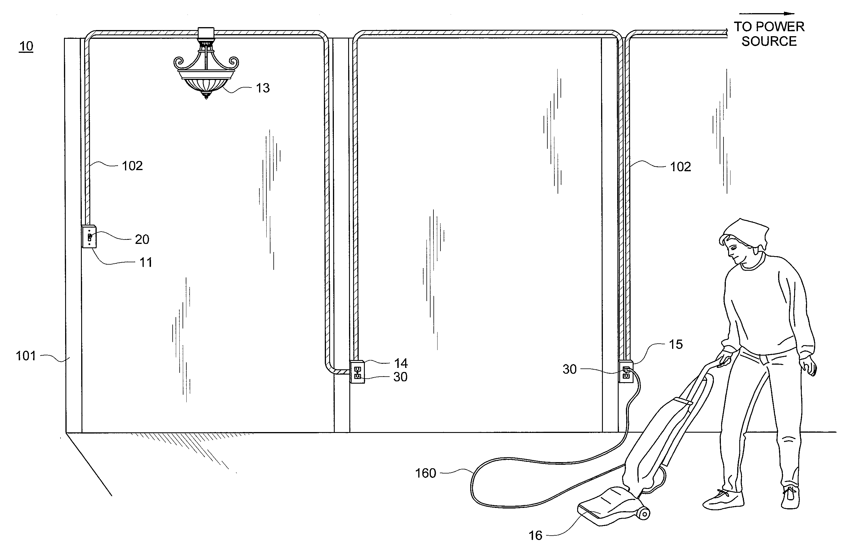
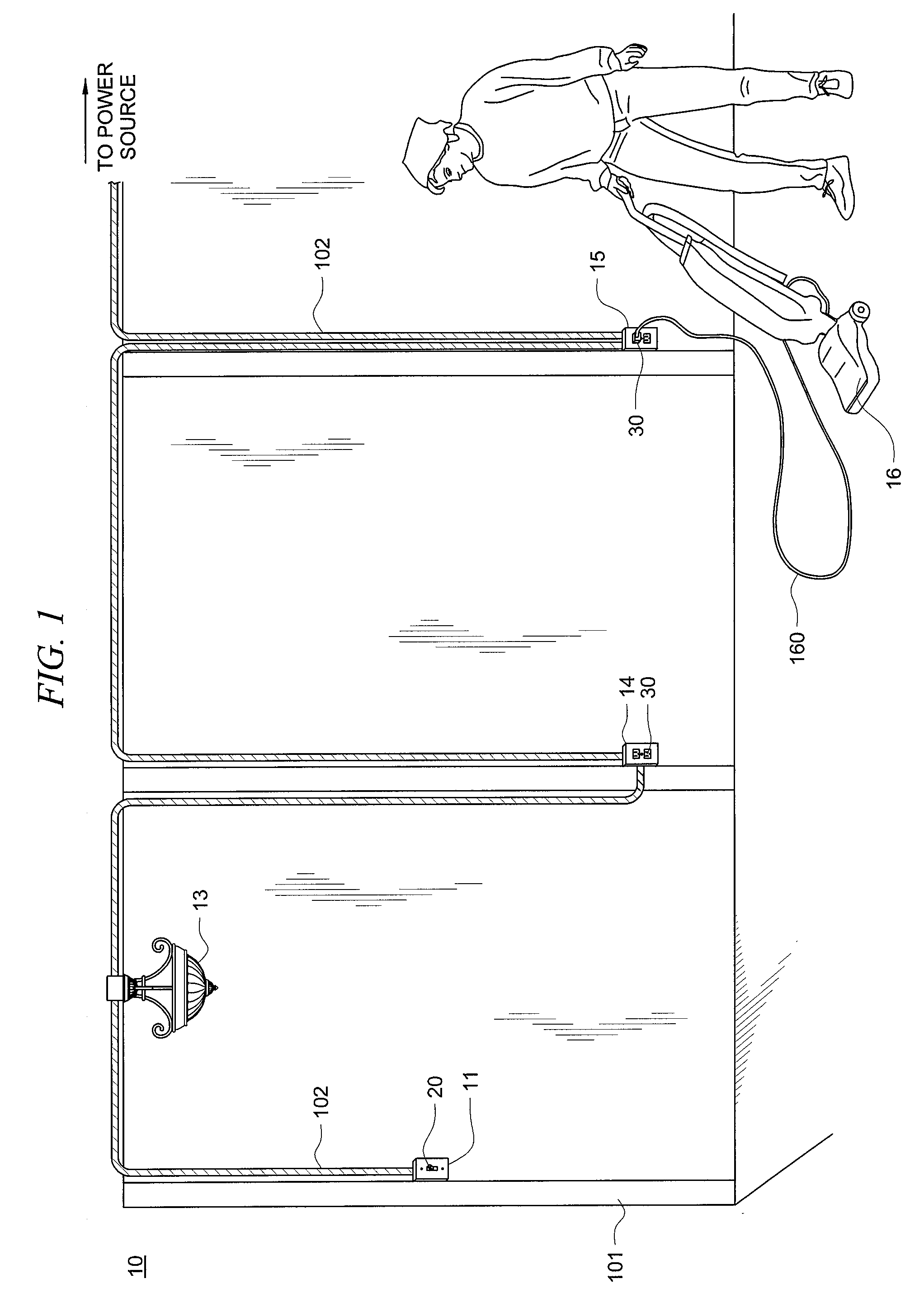
[0020]FIG. 1 shows one embodiment 10 of a premises having end-point power parameter monitoring. Premises electrical wiring 102 is shown, in one embodiment, attached to studding or other framework of the premises. The premises can be a home, office, apartment, industrial building or complex in which a number of locations, such as locations 11, 14 and 15 have electrical control devices, such as devices 20 and 30, positioned thereat. In the embodiment shown, locations 11, 14 and 15 are electrical utility boxes permanently mounted to the premise...


PUM


Abstract

System and methods in which endpoint control devices, such as, for example, switches and wall sockets, are arranged to monitor the power used by the controlled load as well as the power-factor of the load. In one embodiment, the monitored power and power-factor of a controlled device is fed back to a central point within the premises and then sent on to a more global monitoring point. In one embodiment, the endpoint device can send power parameter data to another location and receive instructions as to maximum allowable loads for a given power parameter or power-factor.

Description

CROSS-REFERENCE TO RELATED APPLICATIONS[0001]This application claims priority from U.S. Provisional Patent Application No. 60 / 955,920, entitled “SYSTEMS AND METHODS FOR PREMISES POWER PARAMETER AND POWER-FACTOR REPORTING AND MANAGEMENT” and filed Aug. 15, 2007, the disclosure of which is hereby incorporated herein by reference.TECHNICAL FIELD[0002]This disclosure relates to premises electrical systems and more specifically to systems and methods for premises power, power factor, load factor, power quality reporting and measurement and verification-based load modeling, and even more particularly to endpoint control devices that provide premises power and power-factor reporting control.BACKGROUND OF THE INVENTION[0003]Many systems exist today that provide power and power-factor reporting for a given premises. For example, reference is made to U.S. Pat. No. 7,089,089, U.S. Pat. No. 7,145,439, and U.S. Pat. No. 6,418,419.[0004]For the purpose of this discussion, “Load Profiles” can incl...

Claims


Application Information

Patent Timeline
IPC IPC(8): G01R19/06H02J3/18
CPCG01R22/063G01R21/133
Inventor SCHOETTLE, ROLAND
Owner OPTIMAL INNOVATIONS INC
Why Eureka
Try Eureka