Multi-compatible low and high dynamic range and high bit-depth texture and video encoding system

a texture and video encoding technology, applied in the field of digital image processing, can solve the problems of increasing the level of artifacts in the recovered image, the need to substantially compress the hdr image data, and the additional coding and per-pixel operations, so as to achieve high bit-depth images and reduce the cost of coding. the effect of a single image and a single imag

Active Publication Date: 2009-02-19
TRELLIS EURO SRL
View PDF1 Cites 102 Cited by
  • Summary
  • Abstract
  • Description
  • Claims
  • Application Information

AI Technical Summary

Benefits of technology

[0016]In view of the foregoing, it is an object of the present invention to provide simple, efficient and practical HDR and High Bit-Depth image and video encoding techniques that are both compatible with and can fully exploit existing compression algorithms, including the JPEG and MPEG standards.

Problems solved by technology

Therefore, due to relatively large amount of data for an HDR image, there is a need to substantially compress HDR image data.
The RGBE format explicates a relevant compression problem by introducing the Exponent on a per-pixel basis, since even small errors that may be introduced by common compression methods, such as but not limited to JPEG and MPEG, generate exponentially higher levels of artifacts in the recovered image.
The processes and techniques disclosed in each of the publications identified above disadvantageously call for additional coding and additional per-pixel operations, as well as additional pre- and / or post-correction processing, to achieve satisfactory results.
Moreover, currently available MPEG and / or MPEG4 features and filters cannot be fully and / or easily exploited or employed by, or are incompatible with, many of the processes / systems mentioned above.
With the introduction of high definition (HD) resolutions and bigger display screens—up to 100 inches—the limited precision of standard 24-bit digital images reveals several artifacts on such displays, even when uncompressed.
By employing common compression solutions, like the JPEG or MPEG plethora of algorithms, these artifacts become even more visible to the human eye, due to the reduced precision, in number of bits, of the resulting decompressed output image.
With 8-bit data it is only possible to display 256 shades and moreover with MPEG compression this figure is usually greatly reduced, producing visible banding artifacts when using HD resolutions even on a 26 inches display.
MPEG—and the latest H.264 standard—also introduces block-artifacts due to the nature of the algorithms which encode and store image data in blocks of 4×4 pixels up to 16×16 pixels, which are independent from each other, i.e. the output pixel luma value of a block has no correlation with an adjacent pixel of a different block.
This usually leads to a high luminance contrast between edges of the surrounding blocks.
Such algorithms though are by nature very expensive in terms of the computing power required, which is linearly related to the dimensions of the image to be filtered.

Method used


Image

  • Multi-compatible low and high dynamic range and high bit-depth texture and video encoding system
  • Multi-compatible low and high dynamic range and high bit-depth texture and video encoding system
  • Multi-compatible low and high dynamic range and high bit-depth texture and video encoding system

Examples


example 1

[0050]FRAME.rgb=CHROMA.rgb*f≡FRAME.r=CHROMA.r*fFRAME.g=CHROMA.g*fFRAME.b=CHROMA.b*f

example 2

[0051]FRAME.rgb=CHROMA.rgb*FC.rgb*f≡FRAME.r=CHROMA.r*FC.r*fFRAME.g=CHROMA.g*FC.g*fFRAME.b=CHROMA.b*FC.b*f

[0052]Clamping and “dot” functions employed herein are provided in the “pseudo-code” functions provided below.

Pseudo-Code Functions

[0053]

CLAMP(x, a, b)≡If (x<a) then x=a; else If (x>b) then x=b

DOT(X.rgb, Y.rgb)≡X·Y≡(X.r*Y.r)+(X.g*Y.g)+(X.b*Y.b)

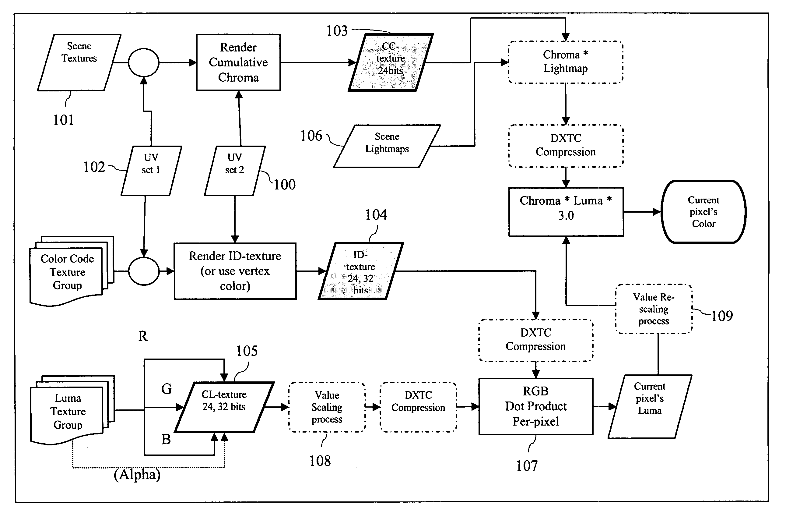
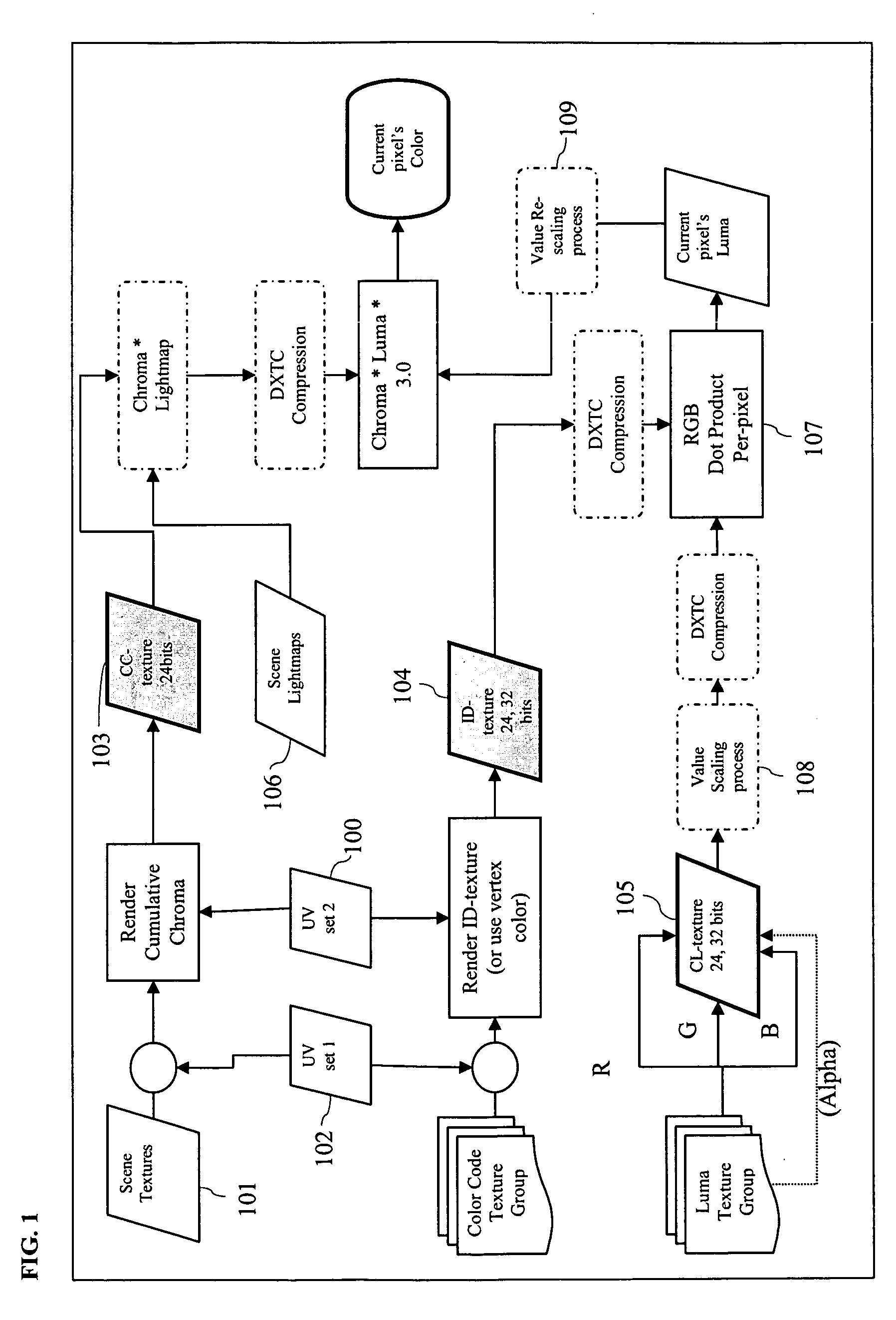
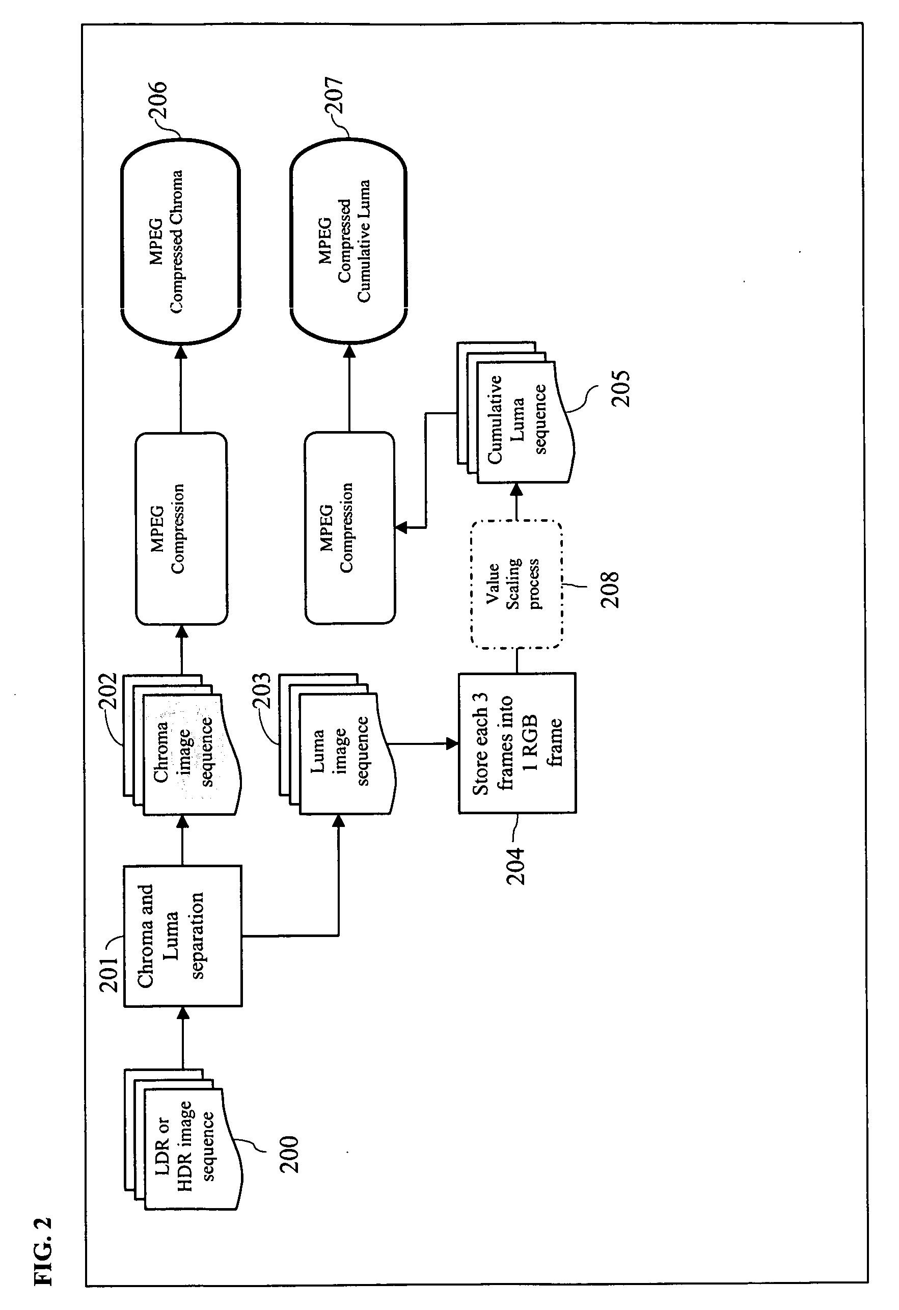
[0054]Each of the figures represents functional block diagrams. Each block within the figures may represent one or more discrete steps / processes that are carried out by one or more devices / systems. Conversely, one device / system may carry out the functions / processes represented by multiple blocks. In various figures, dotted blocks represent optional steps / functionality or possible outputs (after an optional step / functionality is applied). Shaded blocks represent direct encoding outputs.

[0055]As would be appreciated by one of ordinary skill in the art, the herein described processes are particularly well suited for 3D applications. In ...


PUM


Abstract

A method of processing image data includes generating image data including luminance and chrominance data representing a selected object, separating the luminance and chrominance data, storing the separated luminance and chrominance data in corresponding separate spaces in memory, and separately compressing the stored luminance and chrominance data.

Description

CROSS-REFERENCE TO RELATED APPLICATION[0001]The present application claims the benefit of U.S. Provisional Patent Application Ser. No. 60 / 870,509, filed Dec. 18, 2006, and U.S. Provisional Application Ser. No. 60 / 920,053, filed Mar. 26, 2007.FIELD OF INVENTION[0002]The present invention relates to digital image processing and, more particularly, to encoding and decoding low dynamic range (LDR), high dynamic range (HDR) and High Bit-depth images, including video compression.BACKGROUND OF INVENTION[0003]High Dynamic Range Imagery (HDRI) refers to processes, techniques, and digital image systems capable of reproducing real-world lighting and color data with high accuracy. HDRI initially was introduced to overcome dynamic range limitations in digital images, such as described in the scientific publication “Overcoming Gamut and Dynamic Range Limitations in Digital Images” (hereinafter “Ward98—2”), Proceedings of the Sixth Color Imaging Conference, November 1998, as well as in the scienti...

Claims


Application Information

Patent Timeline
Patent Type & Authority Applications(United States)
IPC IPC(8): H04N9/77G06K9/36
CPCG06T9/001G06T9/00H04N19/186H04N19/61H04N19/136H04N19/44H04N19/65
Inventor SALVUCCI, EMANUELE
Owner TRELLIS EURO SRL
Why Eureka
Try Eureka