Unlock instant, AI-driven research and patent intelligence for your innovation.

Failure handling system

Inactive Publication Date: 2009-02-19
FUJITSU LTD
View PDF6 Cites 3 Cited by
  • Summary
  • Abstract
  • Description
  • Claims
  • Application Information

AI Technical Summary

Benefits of technology

[0027]The present invention was created in view of the above circumstances, and an object thereof is to provide a failure handling system capable of properly carrying out failure notification as well as shutoff control for an originating device, thereby improving the operability of an EOS network.

Problems solved by technology

At the same time, Ethernet fails to meet users' needs in many respects, because of its long failure recovery time and the restrictions on transmission distance.
However, the GFP signal propagation function does not allow the EOS host 112 to notify the EOS host 111 of SDH failure, so that the EOS host 111 is unable to control the output of the client device 101, giving rise to a problem that the client device 101 keeps outputting Ethernet frames uselessly.
Also, since the client device 101 is unaware of the failure, the link aggregation function fails to be exercised.
Since RDI-P is always detected in SDH one-way transmission (one-way communication) (in one-way communication, UNEQ-P is transferred at an ADD station, and RDI-P is transferred at a DROP station which receives the UNEQ-P), this case has a problem that RDI-P cannot be used as a condition for the shutoff control.
Thus, in the conventional EOS network system, where an SDH route in the SDH network has failed, the receiving client device for which Ethernet frames are destined can be notified of the failure by virtue of the GFP shutoff control, but the originating client device from which the Ethernet frames are originated is unable to recognize the failure, giving rise to a problem that the originating client device keeps outputting Ethernet frames.

Method used


Image

  • Failure handling system
  • Failure handling system
  • Failure handling system

Examples


Embodiment Construction

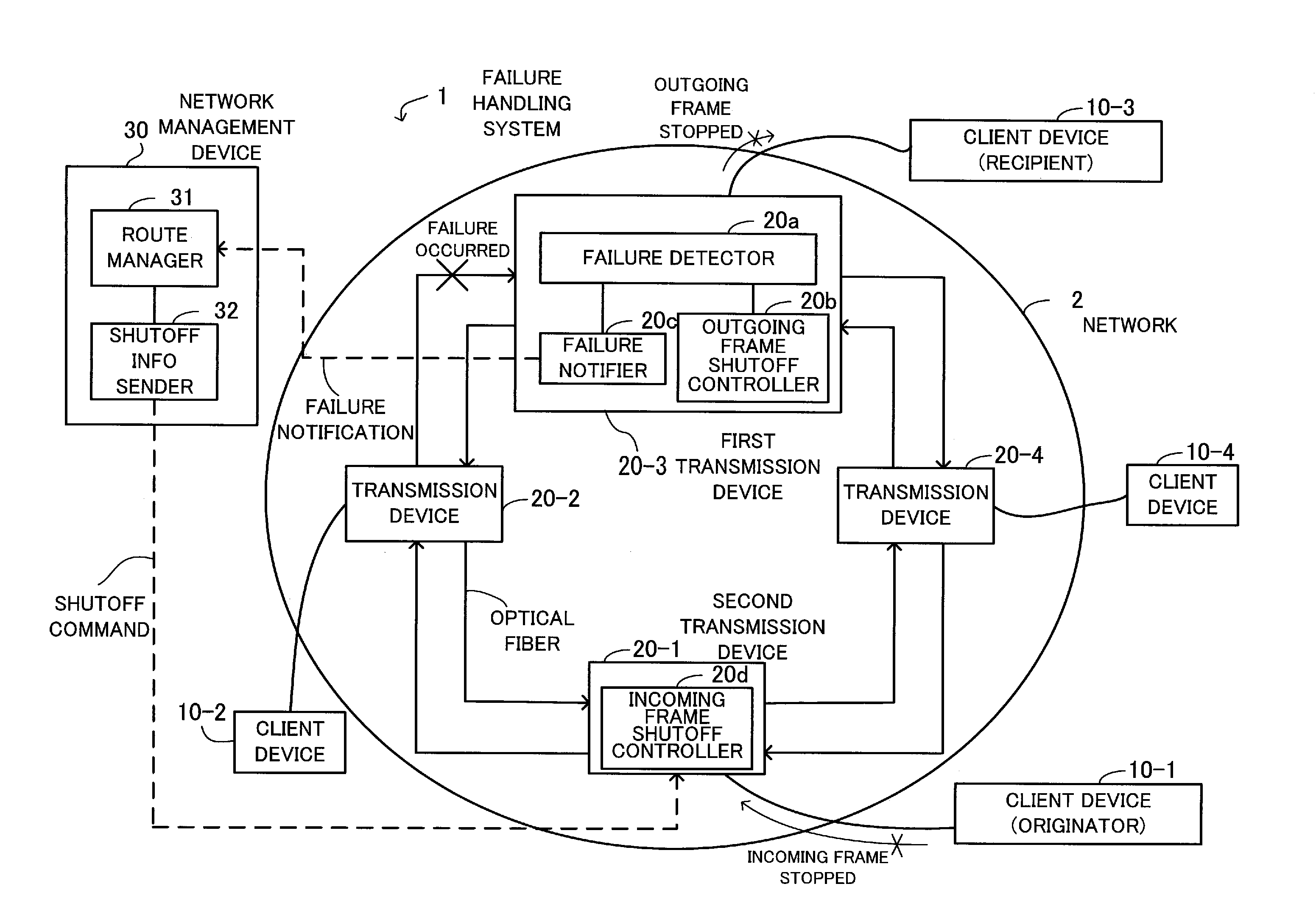
[0046]Preferred embodiments of the present invention will be described below with reference to the accompanying drawings, wherein like reference numerals refer to like elements throughout. FIG. 1 illustrates the principle of a failure handling system according to a first embodiment.

[0047]The failure handling system 1 comprises client devices 10-1 to 10-4, transmission devices 20-1 to 20-4 and a network management device 30, and performs processes (failure notification, shutoff control) related to failure occurring on a network 2.

[0048]The client devices 10-1 to 10-4 are connected to the network 2 (more specifically, the client devices 10-1 to 10-4 are connected to the respective transmission devices 20-1 to 20-4) and exchange communication frames with each other through the network 2. Commonly known client devices are routers (L3 switches), L2 switches, etc.

[0049]The transmission devices 20-1 to 20-4 are connected to each other by two optical fibers so as to form the dual ring netwo...


PUM


Abstract

A failure handling system capable of performing failure notification and shutoff control, thereby improving network operability. When failure is detected, an outgoing frame shutoff controller performs shutoff control on the local device such that the local device stops outputting communication frames to a receiving client device. A failure notifier notifies a network manager that the failure has been detected. On receiving a shutoff command, an incoming frame shutoff controller performs shutoff control on an originating client device such that the originating client device stops outputting the communication frames. A communication route manager manages communication routes through which the client devices communicate with each other across the network. On receiving a failure notification from a first transmission device, a shutoff information sender looks up the communication routes to identify a second transmission device connected with the originating client device, and sends a shutoff command to the second transmission device.

Description

[0001]This application is a continuing application, filed under 35 U.S.C. § 111(a), of International Application PCT / JP2006 / 309004, filed Apr. 28, 2006.BACKGROUND[0002]1. Field[0003]The present invention relates to failure handling systems, and more particularly, to a failure handling system for handling failure occurring on a network.[0004]2. Description of the Related Art[0005]Ethernet (registered trademark) denotes standards commonly used in LANs (Local Area Networks). While 10BASE-T (10 Mbps) is the most popular one among the standards, recent tendency toward higher-speed transmission has increased demand for standards enabling signal transmission at higher rates, such as Fast Ethernet with a transmission rate of 100 Mbps and Gigabit Ethernet with a transmission rate of 1 Gbps or 10 Gbps.[0006]At the same time, Ethernet fails to meet users' needs in many respects, because of its long failure recovery time and the restrictions on transmission distance. Thus, there has been a tren...

Claims


Application Information

Patent Timeline
IPC IPC(8): G01R31/08
CPCH04L12/437
Inventor MIYAZAKI, SATOSHI
Owner FUJITSU LTD
Features
  • R&D
  • Intellectual Property
  • Life Sciences
  • Materials
  • Tech Scout
  • Unparalleled Data Quality
  • Higher Quality Content
  • 60% Fewer Hallucinations
Learn More