Wireless communication method in multiantenna communication system

Inactive Publication Date: 2009-02-19
PANASONIC CORP
View PDF11 Cites 7 Cited by
  • Summary
  • Abstract
  • Description
  • Claims
  • Application Information

AI Technical Summary

Benefits of technology

[0019]According to the present invention, it is possible to increase data transmission throughput when i

Problems solved by technology

There is a high data traffic requirement for the transmissi

Method used


Image

  • Wireless communication method in multiantenna communication system
  • Wireless communication method in multiantenna communication system
  • Wireless communication method in multiantenna communication system

Examples


embodiment 1

[0078]FIG. 3A shows the configuration of a radio communication apparatus on the transmitting side according to Embodiment 1 of the present invention. FIG. 3A shows the configuration when a single data detection mode is adopted. When the single data detection mode is adopted, data of all antennas need to be transmitted upon retransmission.

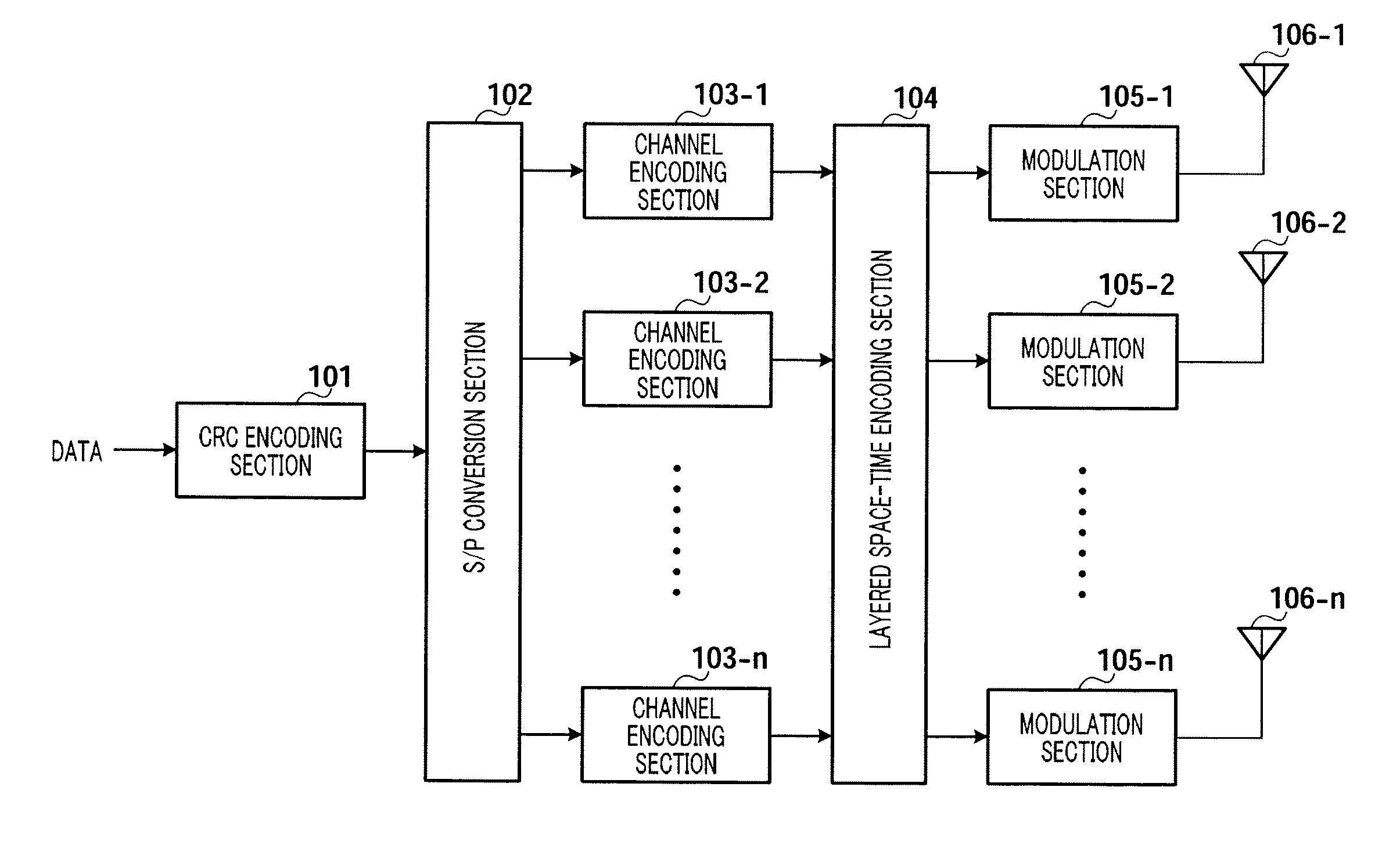
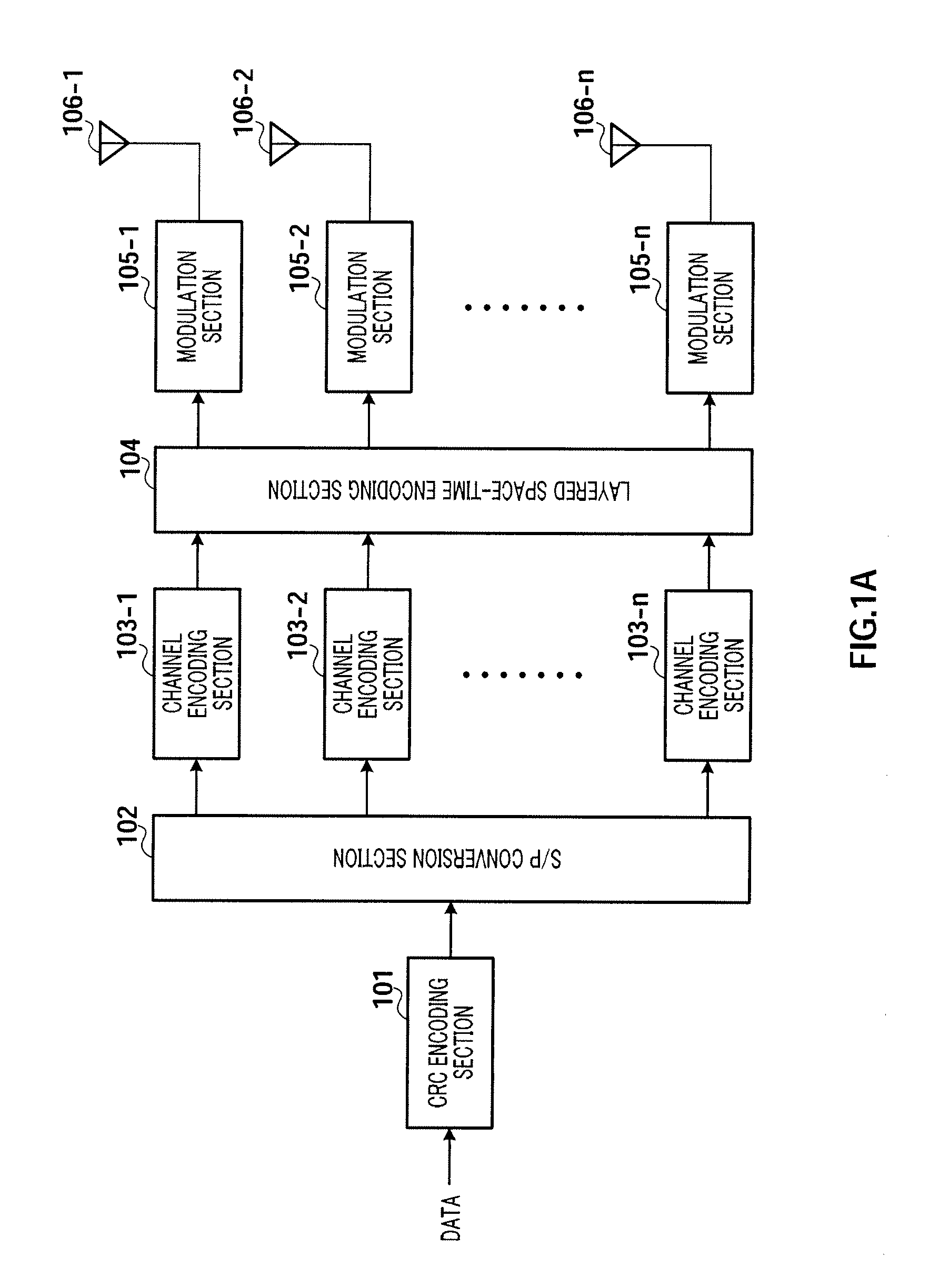
[0079]In FIG. 3A, CRC encoding section 301 carries out CRC encoding on inputted data.

[0080]S / P conversion section 302 S / P-converts CRC-encoded serial data to parallel data streams (substreams).

[0081]Channel encoding sections 303-1 to 303-n carry out channel encoding on respective substreams individually.

[0082]Upon the initial transmission of data, retransmission data processing section 304 carries out no processing, and substreams after channel encoding are directly inputted to layered space-time encoding section 305, respectively.

[0083]Layered space-time encoding section 305 carries out layered space-time encoding on the substreams after channel en...

embodiment 2

[0111]FIG. 5A shows the configuration of a radio communication apparatus on the transmitting side according to Embodiment 2 of the present invention. FIG. 5A shows the configuration when a multi-data detection mode is adopted. In the multi-data detection mode, data of each antenna is CRC-encoded individually, and, if there is an error in data of one antenna, only the data of the one antenna is retransmitted. This allows the amount of retransmission data to be reduced and allows the transmission efficiency to be improved.

[0112]In FIG. 5A, data is S / P-converted to a plurality of parallel substreams by S / P conversion section 501.

[0113]The respective substreams are individually CRC-encoded by CRC encoding sections 502-1 to 502-n and channel-encoded by channel encoding sections 503-1 to 503-n.

[0114]If errors are detected from data of several antennas on the receiving side, the data is inputted to retransmission data processing section 504 upon retransmission. FIG. 5B shows the configura...


PUM


Abstract

A wireless communication method in which use of the HERQ technique brings about an improved throughput of data transmission. In this method, if the number of retransmissions n is equal or below an upper limit value (ST404: NO), a transmission mode k is computed for k=n mod 4 at the transmission side (ST405), sub-streams are grouped into combinations of sub-streams according to the channel status fed back from the transmission side if k=1 (ST 407), time-space block coding of the data of each group is performed (ST 408), the coded data is allocated to the corresponding antenna and retransmitted (ST409), and the retransmitted data is combined with the previously transmitted data and time-space block decoding is performed (ST410).

Description

TECHNICAL FIELD[0001]The present invention relates to a radio communication method in a multi-antenna communication system. More particularly, the present invention relates to a radio communication method which is applied to a MIMO (Multi Input / Multi Output) system and which improves data transmission throughput.BACKGROUND ART[0002]Many new techniques and new applications such as OFDM and MIMO are introduced in mobile communication in recent years. These new techniques drastically improve the mobile communication system performance and meet demands for radio multimedia and high-speed data transmission.[0003]The MIMO technique is a significant breakthrough in a smart antenna technique in the mobile communication field. The MIMO technique refers to a technique realizing both data transmission and reception using a plurality of antennas. By using the MIMO technique, it is possible to improve channel capacities and channel reliability, and reduce bit error rates. A maximum capacity or a...

Claims


Application Information

Patent Timeline
IPC IPC(8): H04B1/02H04L25/49H04J99/00
CPCH04L1/0006H04L1/0625H04L2025/03426H04L25/03343H04L1/1893H04B7/0669H04B7/0697H04L1/1812
Inventor YU, XIAOHONGSHE, XIAOMINGLI, JIFENG
Owner PANASONIC CORP
Why Eureka
Try Eureka