Optical transmission system and dispersion-compensating optical fiber

a technology of optical fiber and transmission system, which is applied in the direction of optical light guides, optical waveguide light guides, instruments, etc., can solve the problems of short transmission distance and inability to achieve high transmission rates

Inactive Publication Date: 2009-02-19
FURUKAWA ELECTRIC CO LTD
View PDF8 Cites 25 Cited by
  • Summary
  • Abstract
  • Description
  • Claims
  • Application Information

AI Technical Summary

Benefits of technology

[0008]It is an object of the present invention to at lea...

Problems solved by technology

Therefore, high transmission rate cannot be achieved and a transmission distance is short.
However, only the C band is used...

Method used


Image

  • Optical transmission system and dispersion-compensating optical fiber
  • Optical transmission system and dispersion-compensating optical fiber
  • Optical transmission system and dispersion-compensating optical fiber

Examples


Embodiment Construction

[0030]Exemplary embodiments of an optical transmission system and a dispersion-compensating optical fiber according to the present invention are explained in detail below with reference to the accompanying drawings. The embodiments do not limit the present invention. Hereinafter, a holey fiber is abbreviated as HF and a dispersion-compensating optical fiber is abbreviated as DCF. In the description, a bending loss means a bending loss on a condition that an optical fiber is wound around a diameter of 20 mm for 16 times. A cutoff wavelength is the fiber cutoff wavelength defined by the ITU-T (International Telecommunication Union Telecommunication Standardization Sector) G.650.1. Other words not specifically defined in the description follow definitions and measuring methods of the ITU-T G.650.1.

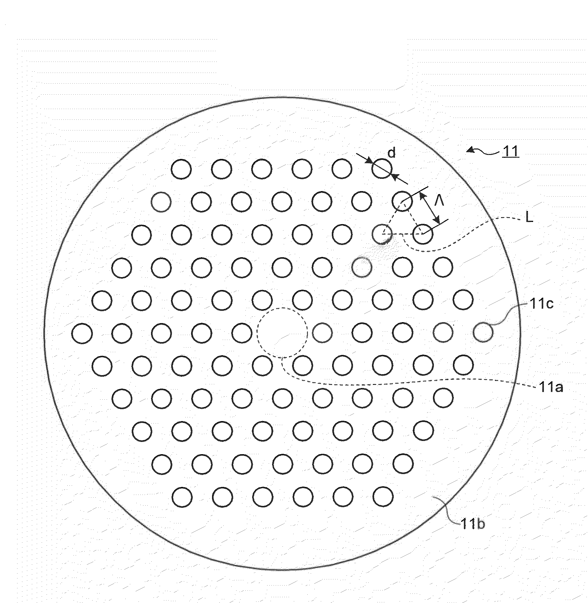
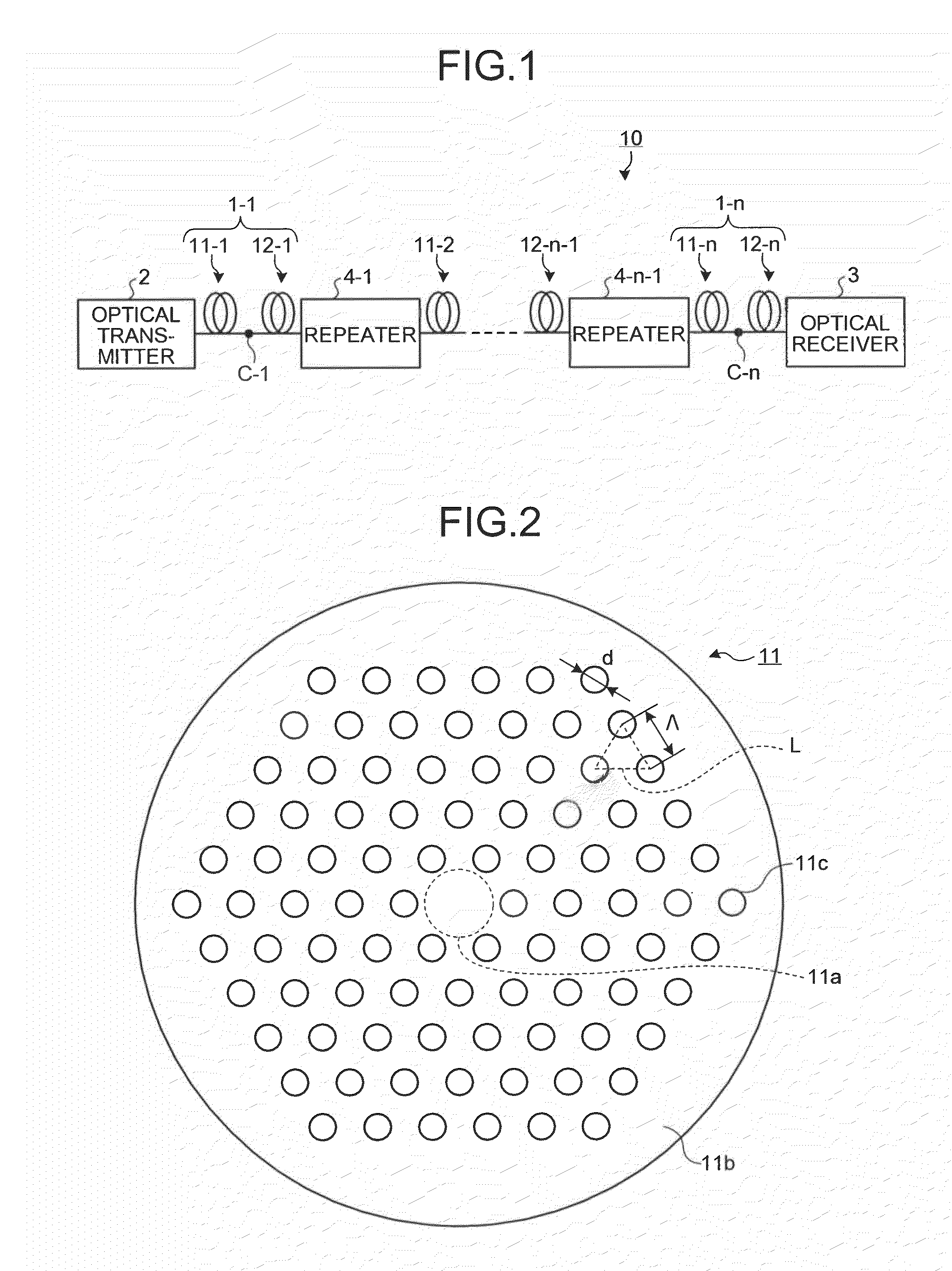
[0031]FIG. 1 is a block diagram of an optical transmission system according to an embodiment of the present invention. As shown in FIG. 1, an optical transmission system 10 according to the e...


PUM


Abstract

An optical transmission system employs an optical fiber as an optical transmission path that includes a holey fiber and a dispersion-compensating optical fiber. The holey fiber includes a core region that is formed at a center of the holey fiber and a cladding region having a plurality of holes around the core region at regular intervals. The dispersion-compensating optical fiber is connected close to the holey fiber and that collectively compensates wavelength dispersion of the holey fiber at an operation wavelength in at least two wavelength bands out of O band, E band, S band, C band, and L band within a predetermined range depending on a transmission rate.

Description

CROSS-REFERENCE TO RELATED APPLICATIONS[0001]This application is a continuation of PCT / JP2008 / 051750 filed on Feb. 4, 2008, the entire content of which are incorporated herein by reference.BACKGROUND OF THE INVENTION[0002]1. Field of the Invention[0003]The present invention relates to an optical transmission system using an optical fiber as an optical transmission path and a dispersion-compensating optical fiber for the optical transmission system.[0004]2. Description of the Related Art[0005]A holey fiber is a new type of optical fiber including a core region formed at a center of the optical fiber and a cladding region having a plurality of holes that are arranged around the core region at regular intervals, where the holes reduce the average refractive index of the cladding region. The light is transmitted in the core region by the principle of the total reflection of light. The holey fiber can achieve special characteristics such as an endlessly single mode (ESM), which cannot be...

Claims


Application Information

Patent Timeline
IPC IPC(8): G02B6/032
CPCG02B6/02261G02B6/02347G02B6/29377G02B6/03644G02B6/0281
Inventor MUKASA, KAZUNORI
Owner FURUKAWA ELECTRIC CO LTD
Why Eureka
Try Eureka