Eureka AIR delivers breakthrough ideas for toughest innovation challenges, trusted by R&D personnel around the world.

Device and a method for adjusting the drilling direction of a tool for drilling an ophthalmic lens

Active Publication Date: 2009-02-19
ESSILOR INT CIE GEN DOPTIQUE
View PDF6 Cites 6 Cited by
  • Summary
  • Abstract
  • Description
  • Claims
  • Application Information

AI Technical Summary

Benefits of technology

[0018]This enables the orientation of the drilling axis of the drilling tool to be adjusted simply and accurately by making use of the degrees of freedom in movement of other members of the drilling and optionally edging machine on which the adjustment device is installed. It is found that the drilling tool can be pivoted about the swivel axis by using the means for providing transverse movements, instead of using specific means that serve solely to pivot the drilling tool. Such means for imparting transverse movements to the drilling tool are in any event needed for adjusting the relative position of the drilling tool relative to the lens in order to position the drilling tool appropriately in register with the location where the lens is to be drilled. In addition, in order to perform this position adjustment, these transverse movement means need to be accurate. Thus, the invention provides a saving in means by giving the transverse movement means not only their main function of adjusting the position of the drilling tool in the plane of the lens, but also a second function of adjusting the orientation of the axis of said drilling tool relative to the lens so as to drill the lens along a desired orientation.
[0024]there is a saving in the overall volume of the machine fitted in this way; and

Problems solved by technology

Amongst the technical and economic difficulties that result from this added function, the main difficulty is due to the fact that drilling of quality that is high, as understood in the profession, needs to be performed in such a manner that the axis of the hole that results from the drilling is normal to the tangent at the point of drilling.
This difficulty has led certain manufacturers purely and simply to eliminate this function of orienting the drilling axis, which then becomes fixed and parallel to the axis of rotation of the lens.
This leads to a function that rapidly presents limits on its suitability for use with lenses that present curvature on the front face.

Method used


Image

  • Device and a method for adjusting the drilling direction of a tool for drilling an ophthalmic lens
  • Device and a method for adjusting the drilling direction of a tool for drilling an ophthalmic lens
  • Device and a method for adjusting the drilling direction of a tool for drilling an ophthalmic lens

Examples


Embodiment Construction

[0026]The following description with reference to the accompanying drawings of an embodiment and given by way of non-limiting example makes it clear what the invention consists in and how it can be implemented.

[0027]In the accompanying drawings:

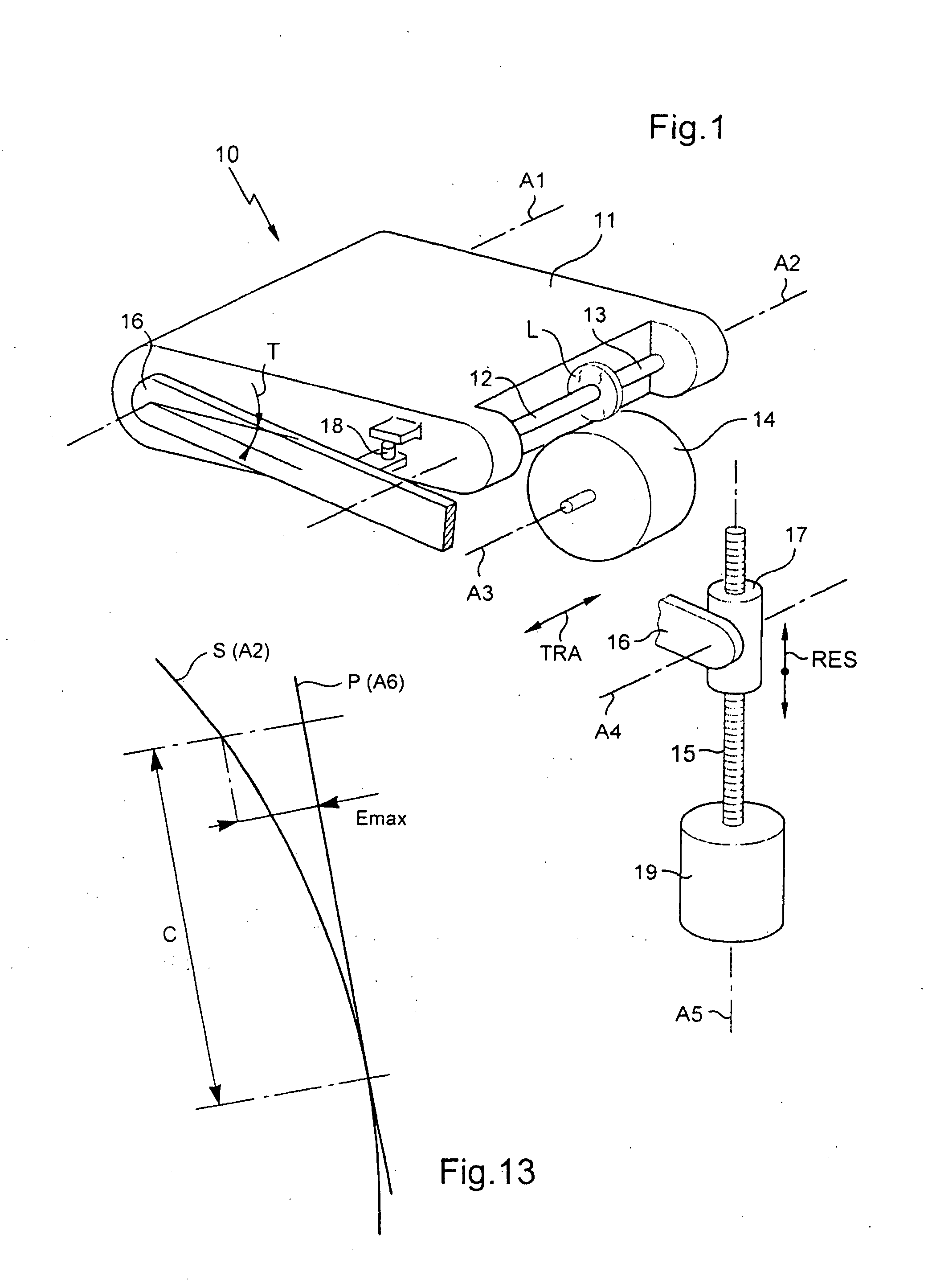
[0028]FIG. 1 is a general diagrammatic view in perspective of an edger;

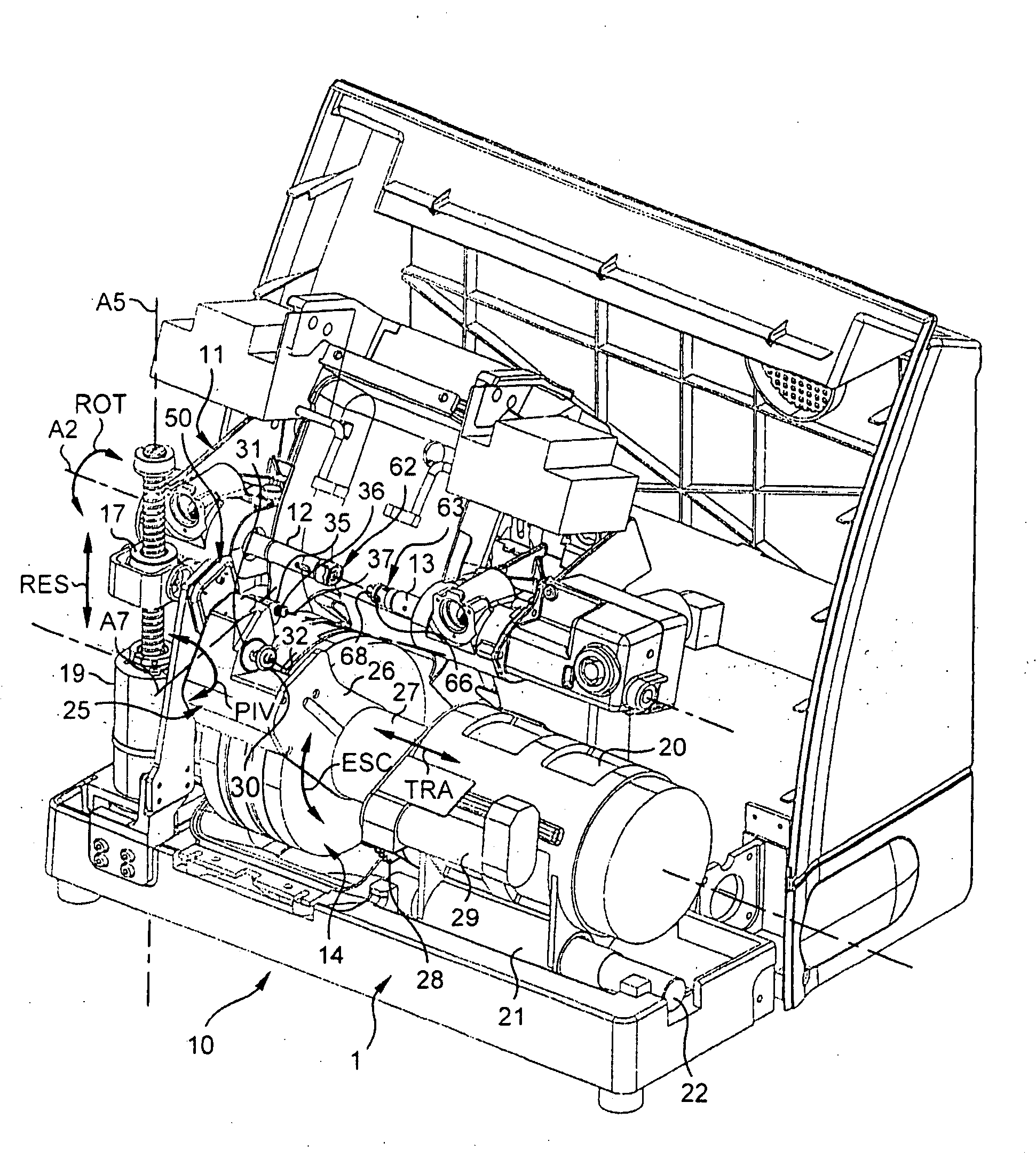
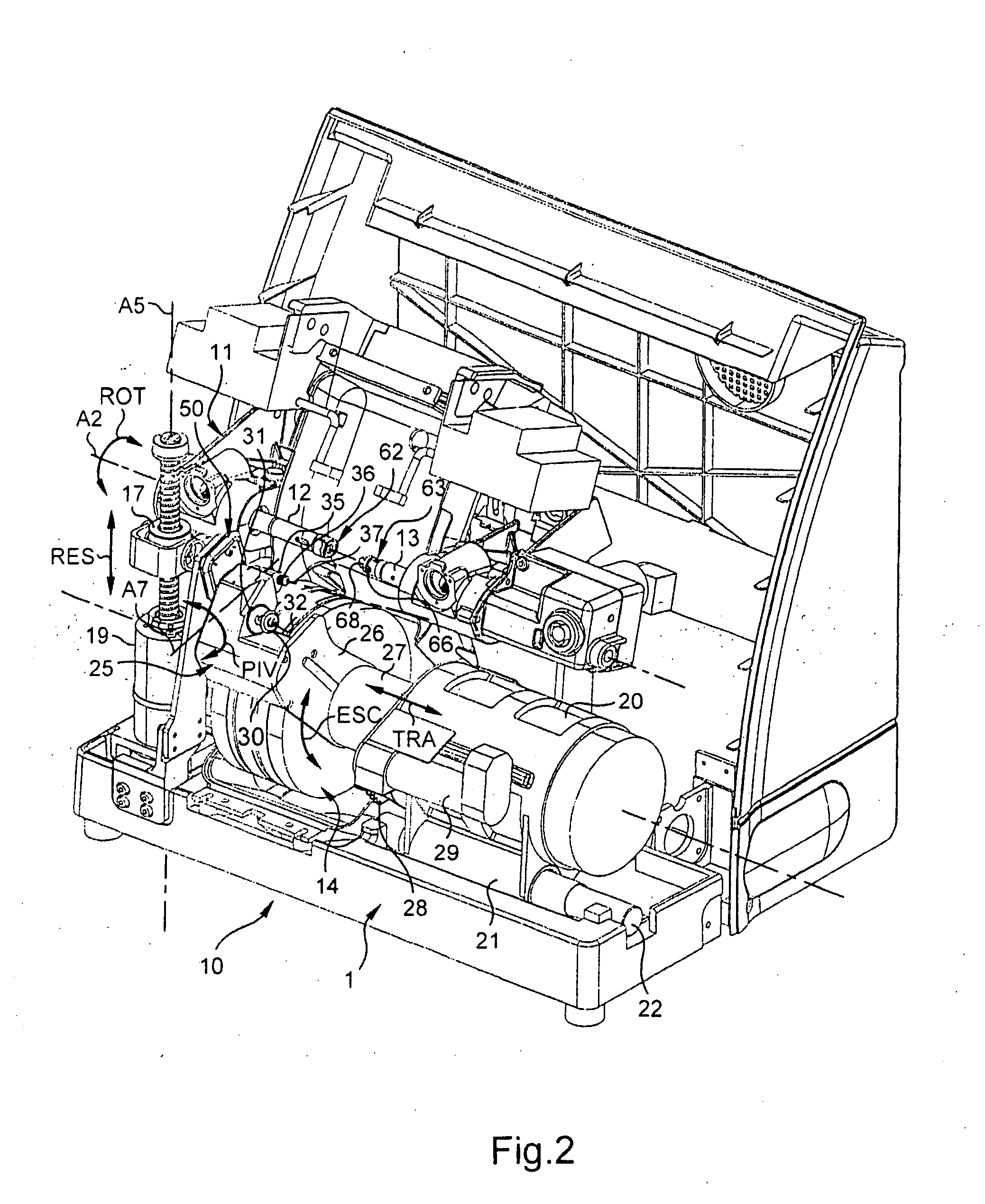
[0029]FIG. 2 is a perspective of an edger fitted with a drill bit and a device for adjusting the orientation of said bit in accordance with the invention;

[0030]FIG. 3 is a fragmentary perspective view of the FIG. 2 edger, seen from another angle and on a larger scale, showing the device for adjusting the orientation of the drill bit, prior to the finger engaging in the orientation ramp;

[0031]FIG. 4 is a detail view in perspective showing the drilling module on its own, from yet another angle;

[0032]FIG. 5 is a section view of the drilling module on plane V of FIG. 4 containing the axis of the drill bit;

[0033]FIG. 6 is a section view on plane VI-VI of FIG. 5, showing in part...


PUM

PropertyMeasurementUnit
Forceaaaaaaaaaa
Frictionaaaaaaaaaa
Torqueaaaaaaaaaa

Abstract

A device includes pivoting elements enabling the drilling axis (A6) of the drilling tool (35) to be pivoted (PIV) about the axis of orientation, and elements for adjusting the angular position of the drilling tool (35) about the axis of orientation. It also includes first mobility members enabling relative mobility of the drilling tool (35) in relation to the lens to be drilled (L), or vice-versa, according to a first degree of mobility (ESC) which is distinct from the pivoting of the drilling axis of the drilling tool (35) about the axis of orientation. The elements for adjustment are configured so as to control the pivoting of the drilling axis (A6) of the drilling tool (35) about the axis of orientation, in favour of the first degree of relative mobility of the drilling tool (35) in relation to the lens (L) that is to be drilled.

Description

TECHNICAL FIELD TO WHICH THE INVENTION RELATES[0001]The present invention relates in general to mounting the ophthalmic lenses of a pair of correcting eyeglasses on a frame, and it relates more particularly to a method and to a device for adjusting the orientation of a tool for drilling an ophthalmic lens.TECHNOLOGICAL BACKGROUND[0002]The technical portion of an optician's profession consists in mounting a pair of ophthalmic lenses in or on a frame that has been selected by the wearer, in such a manner that each lens is properly positioned relative to the corresponding eye of the wearer so as to best perform the optical function for which the lens was designed. To do this, it is necessary to perform a certain number of operations.[0003]Once the frame has been selected, the optician must begin by situating the position of the pupil of each eye in the frame of reference of the frame. The optician thus determines mainly two parameters that are associated with the morphology of the wear...

Claims


Application Information

Patent Timeline
IPC IPC(8): B23B49/00B24B13/005B28D1/14
CPCB24B13/005Y10T409/307672Y10T29/511Y10T408/5614Y10T408/935Y10T408/93Y10T29/5109Y10T29/5107B28D1/14
Inventor NAUCHE, MICHELBARGOT, JEAN-MICHEL
Owner ESSILOR INT CIE GEN DOPTIQUE
Why Eureka
Eureka Blog
Learn More