
Vent Member

Inactive Publication Date: 2009-02-19
NITTO DENKO CORP
View PDF14 Cites 54 Cited by
  • Summary
  • Abstract
  • Description
  • Claims
  • Application Information

AI Technical Summary

Benefits of technology

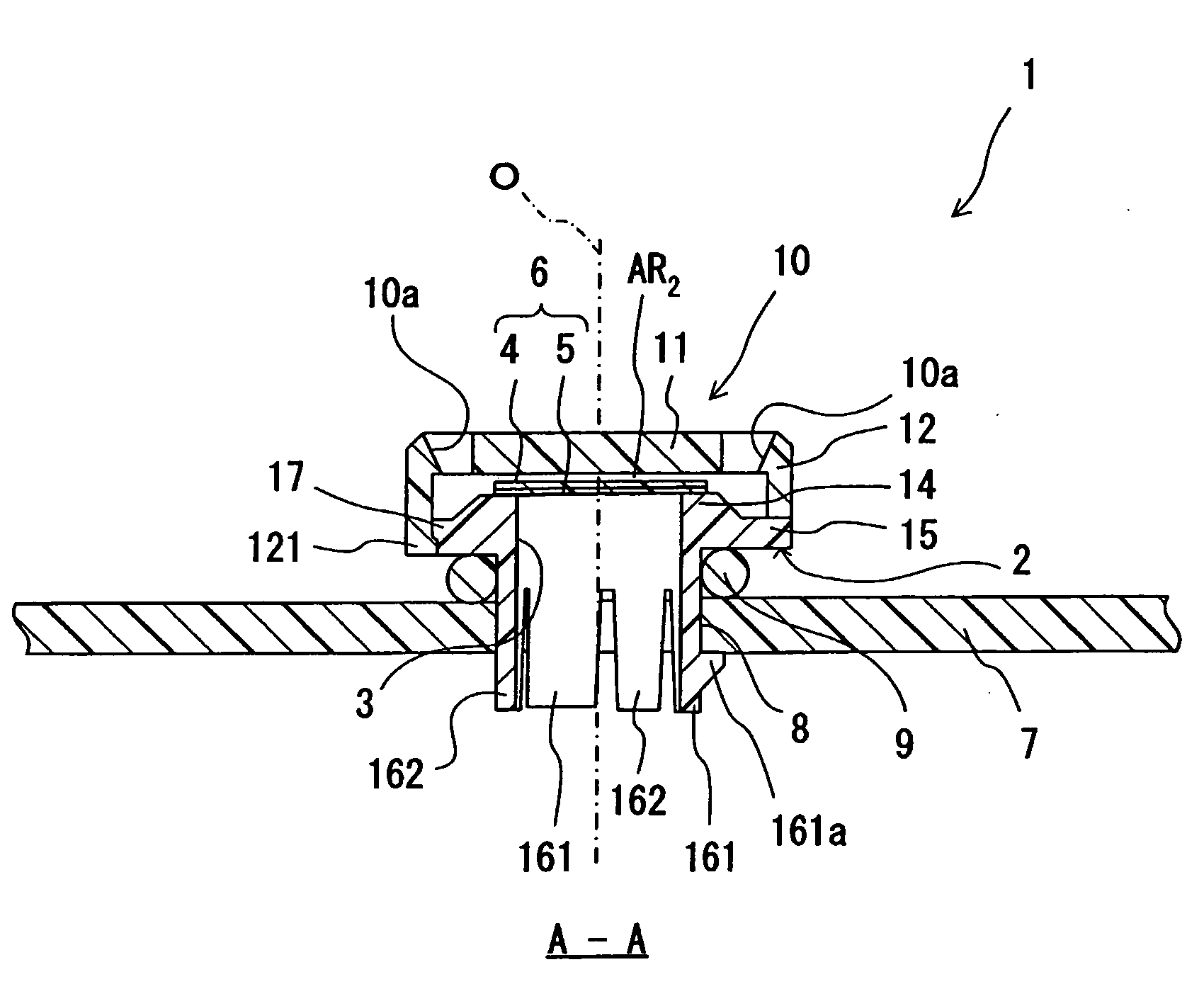
[0010]According to the vent member of the invention, the ventilation hole is made in the ceiling portion of the cover part that protects the permeable membrane. The ventilation hole makes ventilation between the interior and the exterior of the cover part satisfactory. Also, the ventilation hole has a positional relationship in which it does not overlap a permeable region of the permeable membrane in the axial direction. Hence, should foreign matter, such as water droplets coming from the upper side in the axial direction, enter the interior of the cover part through the ventilation hole, the foreign matter is least likely to impinge directly on the permeable membrane. Moreover, by disposing the permeable membrane on the mesa-like portion that is convex to the upper side in the axial direction, it is possible to achieve the configuration that makes it easier to eliminate the foreign matter from the permeable membrane.
[0011]Further, the side wall portion of the cover part protects the permeable membrane entirely along the circumferential direction by extending to the lower side in the axial direction below the position at which the permeable membrane is disposed. Accordingly, as long as a direction is perpendicular to the axial direction (in-plane direction), the permeable membrane is protected in a reliable manner from foreign matter coming from any direction. In addition, a clearance is secured between the side wall portion of the cover part and the support body. To be more specific, it is possible efficiently to discharge water having entered the interior of the cover part through the ventilation hole made in the ceiling portion to the exterior of the cover part through the clearance between the side wall portion of the cover part and the support body. Conversely, it is possible efficiently to discharge water having entered the interior of the cover part through the clearance between the side wall portion of the cover part and the support body to the exterior of the cover part through the ventilation hole made in the ceiling portion of the cover part. In other words, according to the vent member of the invention, in any of the following cases: (i) where the vent member is used in a posture in which the ceiling portion of the cover part is oriented vertically upward; (ii) where the vent member is used in a posture in which the ceiling portion of the cover part is oriented vertically downward; and (iii) where the vent member is used in a posture in which the ceiling portion of the cover part is oriented horizontally, it is possible to achieve the action to discharge water having entered the interior of the cover part to the exterior of the cover part at the same level of efficacy. The limitations of use are therefore relaxed.

Problems solved by technology

However, because it opens widely in the lateral direction, it is highly likely that foreign matter coming from the side applies a direct impact to the permeable membrane 102.
In addition, once the foreign matter adheres onto the permeable membrane 102, it remains on the permeable membrane 102 and can cause deterioration of the permeability.
However, the configuration that resists the entry of foreign matter into the interior of the cover part can bring out an adverse effect in some cases.
More specifically, once the foreign matter enters the interior of the cover part, the foreign matter will not be readily discharged to the exterior of the cover part or it frequently remains on the permeable membrane and on the inner surface of the cover part.
In addition, the vent members disclosed in JP 10-85536A and JP 2001-143524A fail to achieve sufficient dust-proof and water-proof effects unless they are used in a posture in which the cover part is oriented vertically upward.

Method used


Image

  • Vent Member
  • Vent Member
  • Vent Member

Examples


second embodiment

[0056]A vent member 21 shown in FIG. 11 is the same as the vent member 1 described above except that the leg portions 161 and 162 are omitted. The vent member 21 is used in a state where the base portion 15 of a support body 22 is joined directly to the opening 8 of the housing 7 with an adhesive. Although this configuration raises a need to join the components with an adhesive, it is possible to ensure higher air tightness because a problem, such as deterioration of a seal ring, is eliminated. Alternatively, the housing 7 and the vent member 21 may be made into one piece by a known insert molding method by disposing the vent member 21 inside a forming mold used to shape the housing 7. Because the vent member 21 as described above does not use a seal ring, it is possible to reduce an amount of protrusion from the surface of the housing 7 by a comparable amount.

third embodiment

[0057]Advantages similar to those achieved by the vent member 1 shown in FIG. 1 and the other relevant drawings also can be achieved by a vent member 31 shown in FIG. 12. The vent member 31 shown in FIG. 12 includes a mesa-like portion 34 having a surface 34q, which is a curved surface, and a support body 32 including a base portion 35 positioned on the lower side of the mesa-like portion 34. When the permeable membrane 6 is fixed to the mesa-like portion 34 of the support body 32, the surface of the permeable membrane 6 is changed to a slightly curved shape by following the mesa-like portion 34. Accordingly, water hardly remains on the permeable membrane 6 whose surface is thus curved.


PUM


Abstract

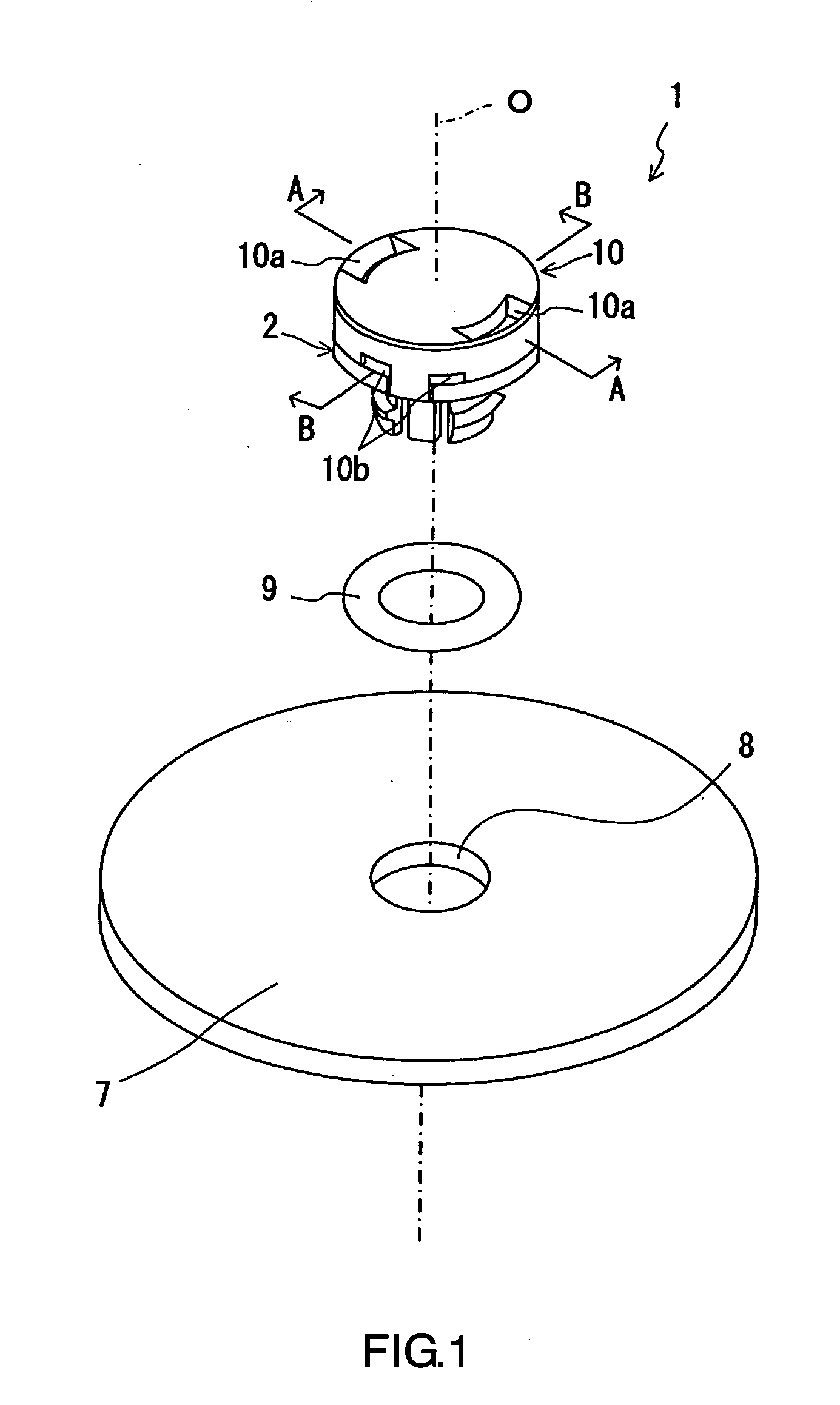
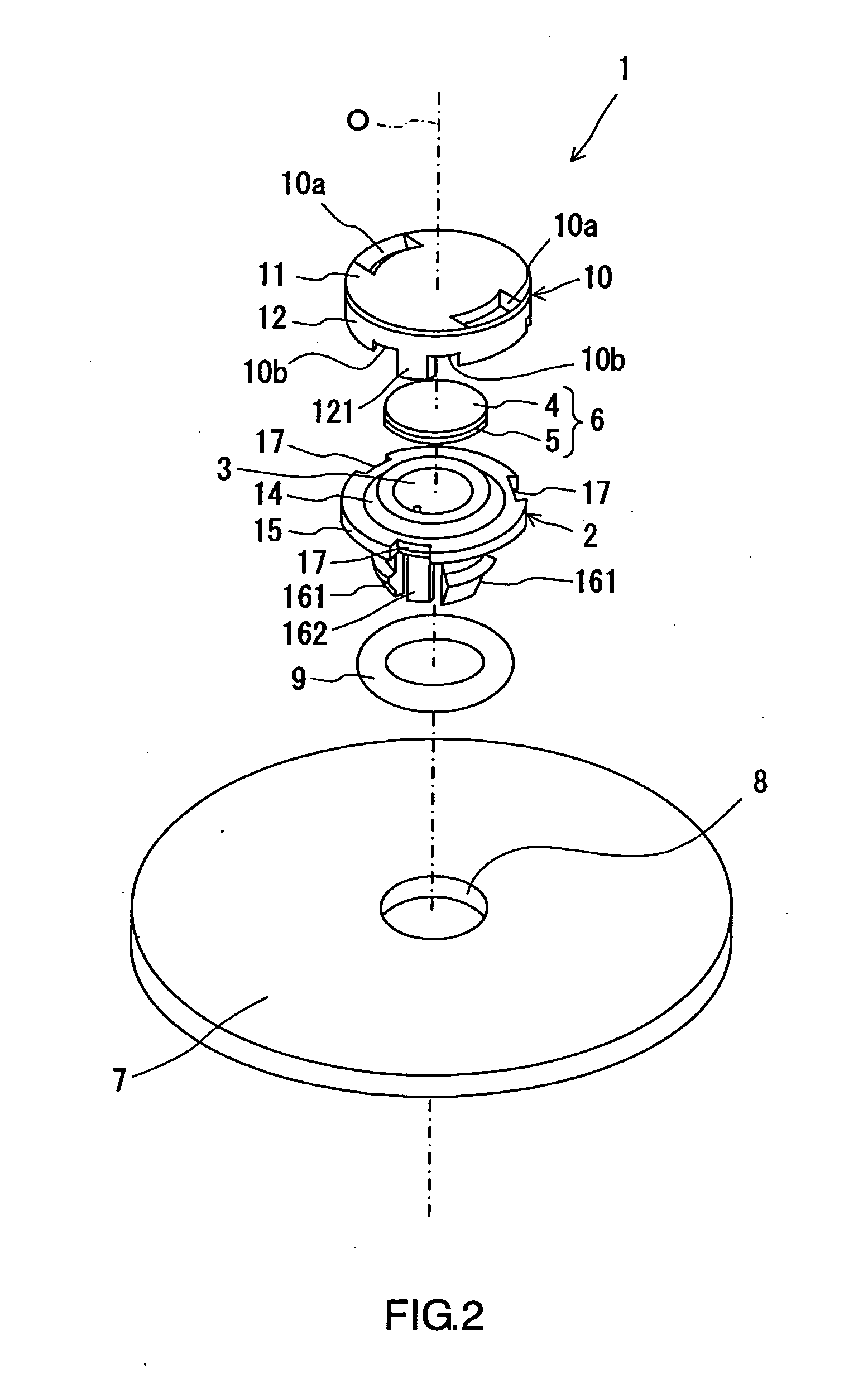
A vent member (1) includes a support body (2) provided with a through-hole (3), a permeable membrane (6) closing the through-hole (3) in the support body (2), and a cover part (10) covering the permeable membrane (6). A ventilation hole (10a) is made in a ceiling portion (11) of the cover part (10) and a notch (10b) is made in a side wall portion (12) thereof. These ventilation hole (10a) and notch (10b) function as a passage for ventilation between the interior and the exterior of the cover part (10). The ventilation hole (10a) establishes a positional relation that it does not overlap a permeable region of the permeable membrane (6) in the axial direction. Further, the side wall portion (12) extends to the lower side in the axial direction below a position at which the permeable membrane (6) is disposed, and the permeable membrane (6) is protected entirely along a circumferential direction by the side wall portion (12). The permeable membrane (6) is disposed on a mesa-like portion (14) that is convex to the upper side in the axial direction.

Description

TECHNICAL FIELD[0001]The present invention relates to a vent member attached to a housing.BACKGROUND ART[0002]Vent members are attached to housings that accommodate therein electrical components of an automobile, such as lamps, sensors, and ECUs, in order not only to ensure ventilation between the interior and the exterior of the housings but also to prevent the entry of foreign matter into the interior of the housings. Examples of such vent members are disclosed in JP 2004-47425A, JP 10-85536A, and JP 2001-143524A.[0003]For instance, as is shown in FIG. 14, the vent member disclosed in JP 2004-47425A includes a support body 103 on which a permeable membrane 102 is disposed and a cover part 104 attached to the support body 103 so as to cover the permeable membrane 102. The vent member 101 configured as above is fixed to an opening 107 of a housing 106 via an O-ring 105. By allowing a gas to permeate through the permeable membrane 102, it is possible to ensure ventilation between the...

Claims


Application Information

Patent Timeline
IPC IPC(8): B60H1/24F21V31/03B60R16/02
CPCB65D77/225F21S48/335F21S48/337F21S48/332H02K2205/09H05K5/0213F21V31/03H02K5/10F21S45/30H05K5/0216B60R16/02
Inventor YANO, YOUZOUSHIMAZAKI, YUUTANISHIMORI, TOSHIMASASUGOU, YUUKIIKEYAMA, YOSHIKI
Owner NITTO DENKO CORP
Features
  • Generate Ideas
  • Intellectual Property
  • Life Sciences
  • Materials
  • Tech Scout
  • Unparalleled Data Quality
  • Higher Quality Content
  • 60% Fewer Hallucinations
Learn More