Proactive optical wind shear protection and ride quality improvement system

a technology of optical wind shear protection and protection system, applied in the field of flight control avionics, can solve the problems of unmet needs in the art for a system, increased operational errors, and frequent turbulence of aircraft, and achieves the effects of improving the ride quality of passengers, and reducing the effect of turbulen

Inactive Publication Date: 2009-02-19
THE BOEING CO
View PDF2 Cites 43 Cited by
  • Summary
  • Abstract
  • Description
  • Claims
  • Application Information

AI Technical Summary

Benefits of technology

[0014]Embodiments of the present invention provide systems and methods for proactively protecting against wind shear and severe turbulence as well as improving ride quality of an aircraft. By detecting and proactively responding to wind shear and turbulence, the present invention automatically compensates control of an aircraft for wind shear or turbulence as the aircraft encounters the win

Problems solved by technology

For example, aircraft frequently encounter turbulence during flight.
Therefore, a potential is created for operational errors and sub-optimal aircraft performance.
However, there is an unmet need in the art for a system that proactively corrects for turbulence in an aircraft that is following a trajectory.
Furthermore, manned aircraft frequently encounter turbulence during flight.
However, currently known attempts to mitigate effects of turbulence are reactive.
However, such an approach is complicated, expensive, and adds significant weight to an aircraft.
More commonly, pilots report occurrences of turbulence when the turbulence is encountered.
Therefore, currently known attempts to mitigate effects of turbulence are reactive and either expensive, complicated, and heavy, or rely upon empirically-determined information that may be outdated when the turbulence is eventually encountered.
Clear air turbulence can cause aircraft to gain or lose noticeable amounts of altitude rapidly.
In severe cases, items that are not securely stowed or, in extremely severe cases, passengers or flight crew who are not wearing

Method used


Image

  • Proactive optical wind shear protection and ride quality improvement system
  • Proactive optical wind shear protection and ride quality improvement system
  • Proactive optical wind shear protection and ride quality improvement system

Examples


Embodiment Construction

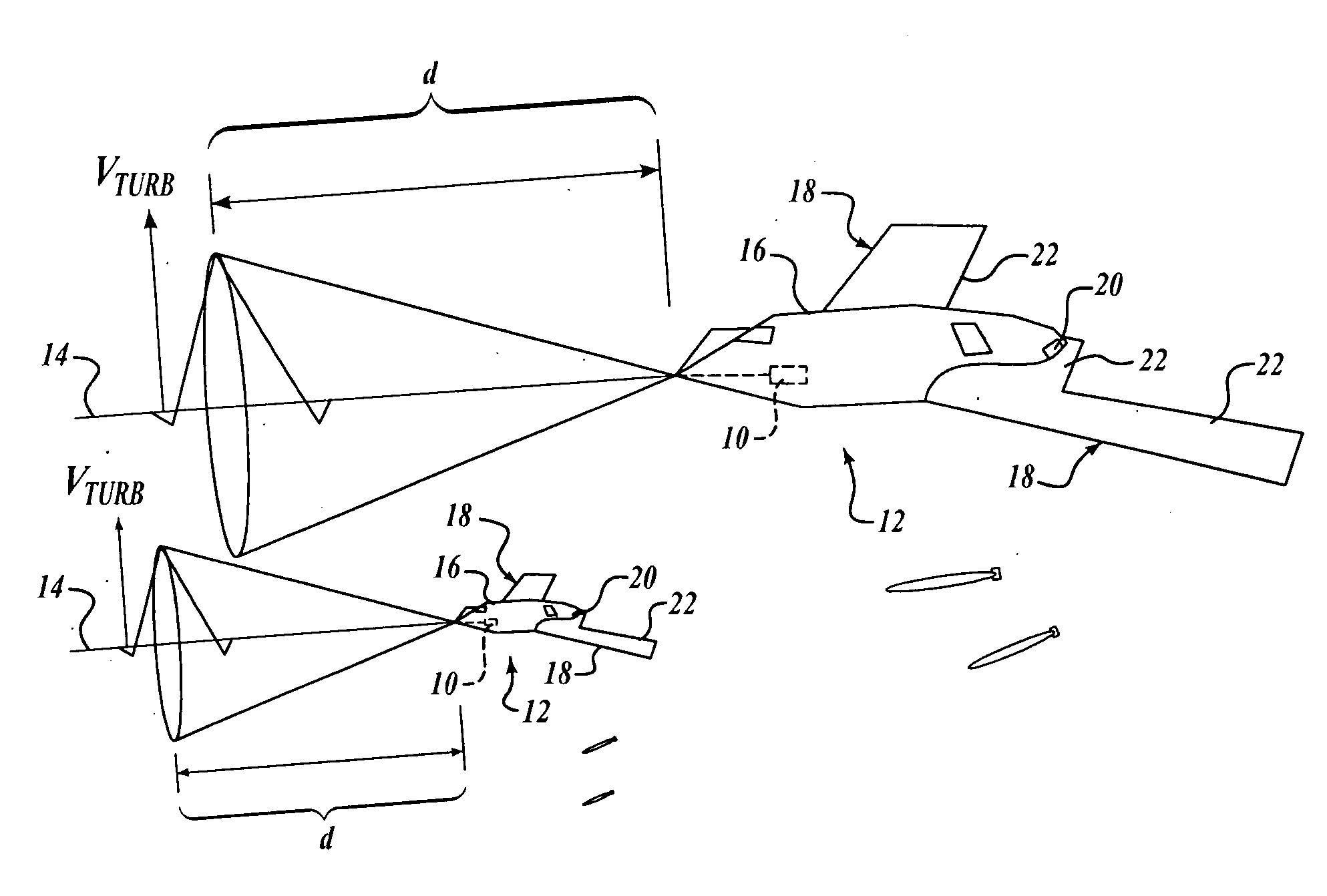
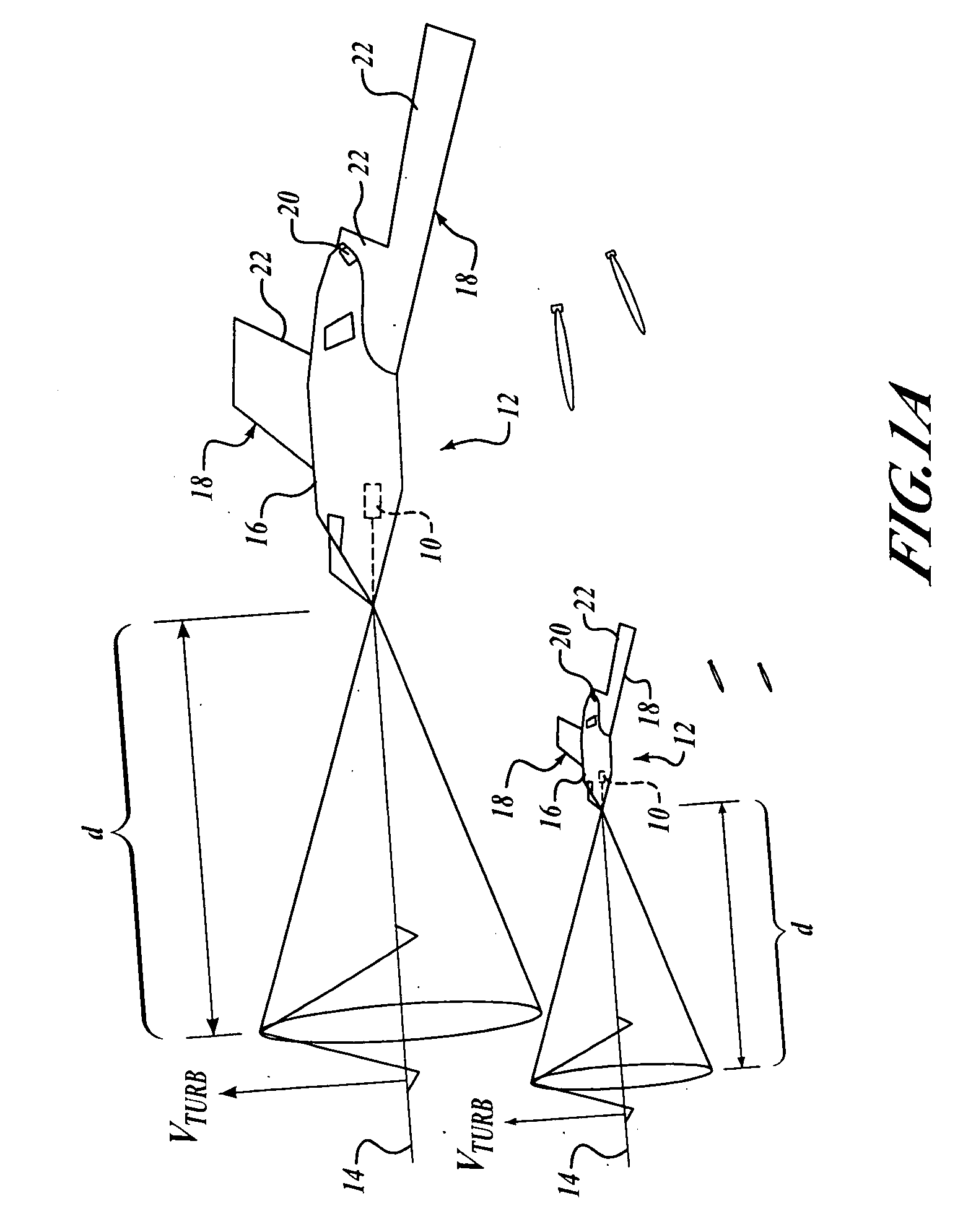
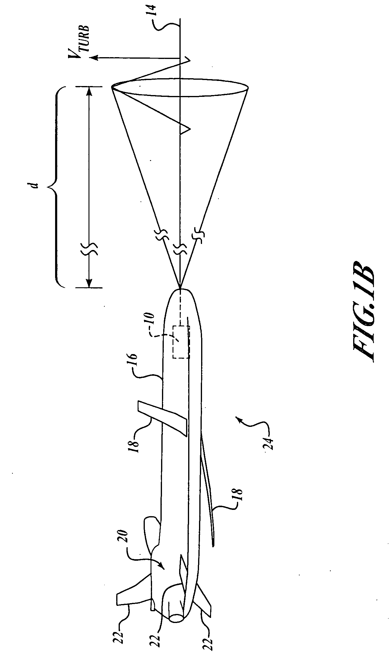
[0033]By way of overview, embodiments of the present invention automatically correct flight path of an aircraft onto a predetermined trajectory. A sensor is configured to sense speed of air relative to the aircraft at a predetermined distance in front of the aircraft. A navigation system is configured to determine displacement of a flight path of the aircraft from the predetermined trajectory. A processor is coupled to receive the sensed speed of air from the sensor and the displacement of the flight path from the navigation system. The processor includes a first component that is configured to determine whether the speed of the air at the predetermined distance is indicative of turbulence, and a second component that is configured to automatically generate control signals to correct the flight path of the aircraft from the displacement onto the predetermined trajectory by a time when the aircraft enters the turbulence.

[0034]Referring now to FIG. 1A, an exemplary system 10 according...


PUM


Abstract

Embodiments of the present invention automatically compensate control of an aircraft for an environmental condition, such as turbulence or wind shear. A sensor is configured to sense speed of air relative to an aircraft at a predetermined distance in front of the aircraft. A processor is coupled to receive the sensed speed of air from the sensor. The processor includes a first component configured to determine whether the speed of the air at the predetermined distance is indicative of an environmental condition, such as turbulence or wind shear. A second component is configured to automatically generate control signals for controlling the aircraft such that the environmental condition is automatically compensated by a time the aircraft enters the environmental condition.

Description

CROSS-REFERENCE TO RELATED APPLICATIONS[0001]This application is a Continuation-in-part of application Ser. No. 10 / 633,353 filed on Jul. 31, 2003 and application Ser. No. 10 / 633,346 filed on Jul. 31, 2003, the contents of both of which are incorporated by reference.FIELD OF THE INVENTION[0002]The present invention relates generally to avionics and, more specifically, to flight control avionics.BACKGROUND OF THE INVENTION[0003]Various types of aircraft follow a predetermined trajectory during flight for a variety of reasons. For example, a missile follows a predetermined trajectory to reduce errors in the missile's point of impact. In this example, improving impact error results in a performance improvement for the missile and a safety improvement by possibly reducing any unintended collateral damage that may result from an erroneous impact point.[0004]Other aircraft also follow predetermined trajectories. For example, unmanned air vehicles, such as drones, follow predetermined traje...

Claims


Application Information

Patent Timeline
IPC IPC(8): G05D1/00B64C13/16B64D31/06F41G7/26G01J1/42G05D1/03
CPCB64C13/16G05D1/0615B64D31/06G01S17/58G01S17/95Y02A90/10
Inventor NUGENT, MARK R.SINAI, MASSOUD
Owner THE BOEING CO
Why Eureka
Try Eureka