Thermally powered turbine inlet air chiller heater

a technology of inlet air chiller and turbine, which is applied in the direction of machines/engines, lighting and heating apparatus, machine operation mode, etc., can solve the problems of attendant capital cost and operating cost, potentially harmful icing,

Inactive Publication Date: 2009-02-26
ERICKSON DONALD CHARLES +1
View PDF14 Cites 34 Cited by
  • Summary
  • Abstract
  • Description
  • Claims
  • Application Information

AI Technical Summary

Problems solved by technology

At inlet temperatures below about 40° F., such cooling of the air can lead to potentially harmful icing whenever the relative humidity is above about 70%.
Prior art turbine inlet air heaters have used electric resistance heating, compressor bleed air, steam heating, exhaust heated air, and the like, with attendant capital cost and operating cost.

Method used


Image

  • Thermally powered turbine inlet air chiller heater
  • Thermally powered turbine inlet air chiller heater
  • Thermally powered turbine inlet air chiller heater

Examples


Embodiment Construction

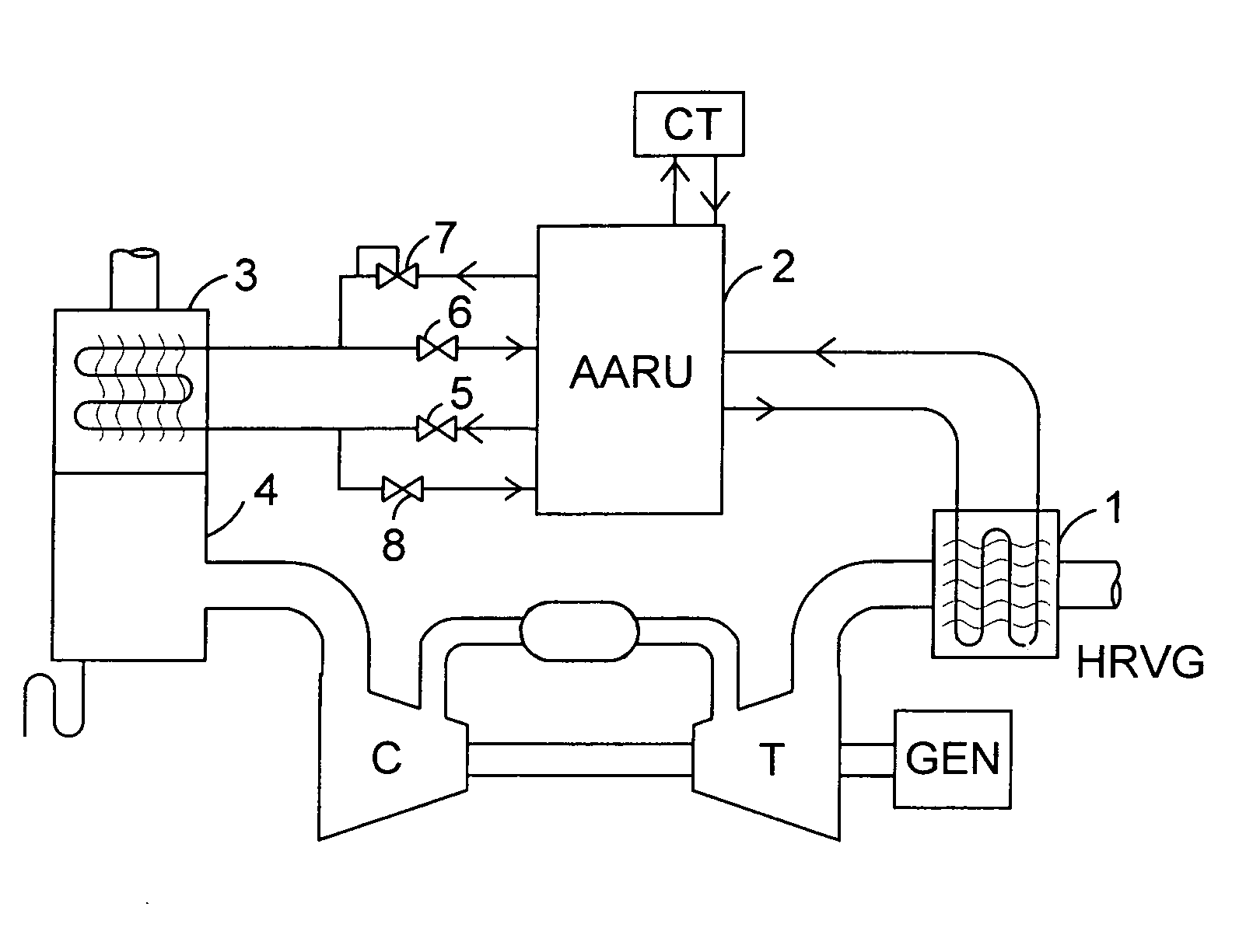
[0012]There are several ways the thermally powered compressor inlet air chilling system can be modified to add an air heating function, as shown by the following examples.

[0013]FIG. 1 is a schematic flowsheet of a combustion turbine system including a thermally activated inlet air chilling system. In addition to the compressor, combustor, and expansion turbine, the system is comprised of an exhaust heat recovery unit 1, which supplies turbine exhaust heat to the thermally activated system 2; and an inlet air exchanger 3, that chills the inlet air with refrigerant produced in the thermally activated system. A water separator and demister 4 is located at the outlet of the exchanger, to prevent water droplets from entering the compressor. In normal chilling operation, a liquid refrigerant supply valve 5, e.g. an expansion valve, supplies liquid refrigerant to the cold end of the exchanger, and vapor from the warm end is routed back to the thermally activated system. On cold days, when ...


PUM


Abstract

An improvement to the air compressor of a combustion turbine system is disclosed, which makes the air compression more energy efficient plus have higher capacity on warm days. The same equipment with minimal modification is used to prevent inlet air icing conditions on cold days. Referring to FIG. 1, inlet air conditioner 3 supplies conditioned (chilled or heated) air to the combustion turbine, and heat recovery unit 1 supplies turbine exhaust heat to ammonia absorption refrigeration unit 2. Control valves 5, 6, 7, and 8 selectively supply either chilling refrigerant liquid or heating vapor to conditioning coil 3.

Description

CROSS REFERENCE TO RELATED APPLICATIONS[0001]Not ApplicableSTATEMENT REGARDING FEDERALLY SPONSORED RESEARCH AND DEVELOPMENT[0002]Not ApplicableBACKGROUND OF THE INVENTION[0003]Combustion turbines benefit substantially from chilling the inlet air on warm days. Both capacity and efficiency improve. The improvements are maximized by using turbine waste heat to supply the chilling, in lieu of mechanical power. Examples of this are found in U.S. Pat. No. 6,739,119; 6,457,315; and 5,782,093.[0004]As the inlet air accelerates in the bellmouth, it experiences adiabatic cooling. At inlet temperatures below about 40° F., such cooling of the air can lead to potentially harmful icing whenever the relative humidity is above about 70%. Accordingly, high performance turbines advantageously have means for heating such cold, moist air. Only about 10 to 15° F. temperature increase is required to reduce the relative humidity from 100% to below 70% when the ambient temperature is 40° F. or lower.[0005]...

Claims


Application Information

Patent Timeline
Patent Type & Authority Applications(United States)
IPC IPC(8): F02C7/14
CPCF02C7/047F02C7/143Y02B30/625F25B27/02F25B29/006F25B15/04Y02A30/274
Inventor ERICKSON, DONALD CHARLESANAND, GOPALAKRISHNAN
Owner ERICKSON DONALD CHARLES
Why Eureka
Try Eureka