Device for applying a suspension onto a base plate

a suspension and base plate technology, applied in the field of suspension devices, can solve the problems of increasing production costs, no longer using suspensions, and relatively long dwell time in reservoirs, and achieve the effect of ensuring the distribution accuracy of suspensions to be applied

Inactive Publication Date: 2009-02-26
FLOORING TECH
View PDF57 Cites 7 Cited by
  • Summary
  • Abstract
  • Description
  • Claims
  • Application Information

AI Technical Summary

Benefits of technology

[0007]Based on the above problem, the invention provides an improved device such

Problems solved by technology

The disadvantage of such a device is that a reservoir of the suspension to be applied must be placed upstream in the direction of rotation of the doctor blade located on the metering roll, in order to guarantee an application that is uniform over the entire width of the roll.
A relatively large amount of the suspension, e.g., c

Method used


Image

  • Device for applying a suspension onto a base plate
  • Device for applying a suspension onto a base plate
  • Device for applying a suspension onto a base plate

Examples


Embodiment Construction

[0024]The particulars shown herein are by way of example and for purposes of illustrative discussion of the embodiments of the present invention only and are presented in the cause of providing what is believed to be the most useful and readily understood description of the principles and conceptual aspects of the present invention. In this regard, no attempt is made to show structural details of the present invention in more detail than is necessary for the fundamental understanding of the present invention, the description taken with the drawings making apparent to those skilled in the art how the several forms of the present invention may be embodied in practice. The embodiment described below uses a belt and chain drive as transmission steps by way of example. However, the mechanisms described can also be applied to gear trains.

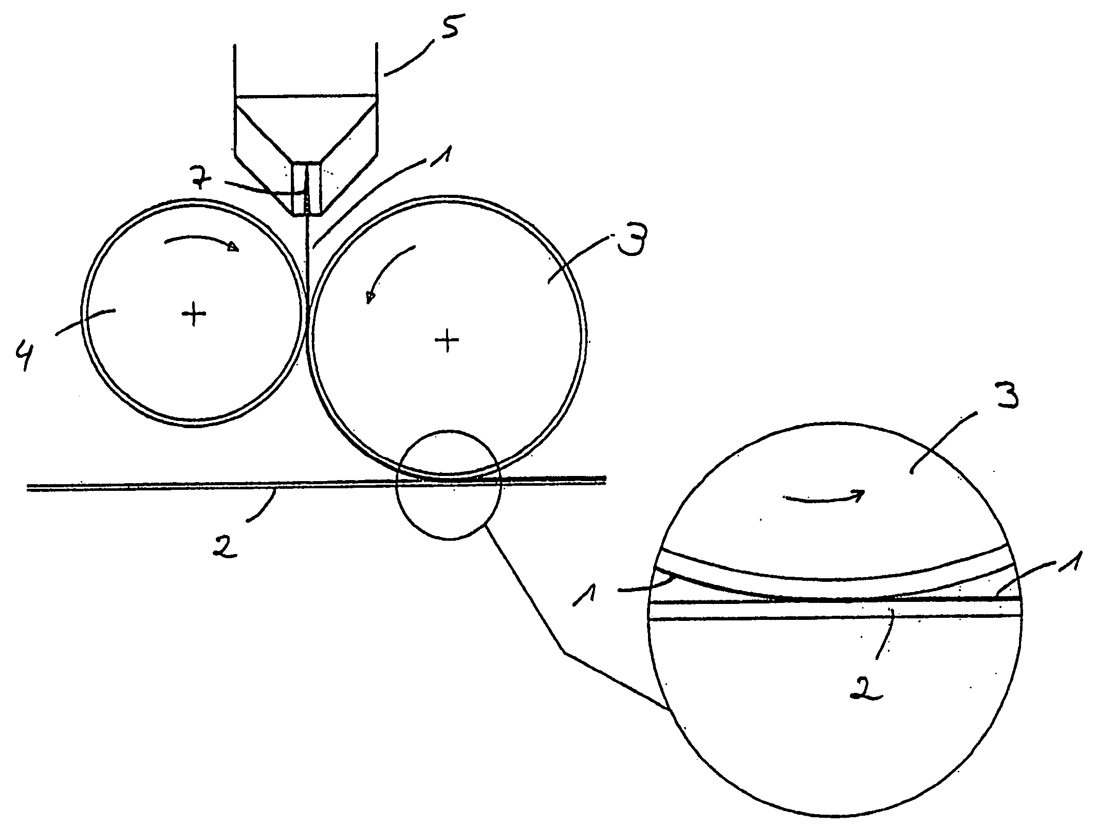
[0025]FIG. 1 shows a device according to the invention in side view. FIG. 1 shows a suspension 1 to be applied onto a base plate 2 as it exits from slots...


PUM

PropertyMeasurementUnit
Angleaaaaaaaaaa
Angleaaaaaaaaaa
Angleaaaaaaaaaa

Abstract

A device for applying a suspension to which particles, in particular corundum particles, have been added onto a base plate, with a roller mill comprising an applicator roll and a metering roll interacting with the applicator roll. An application groove with two groove halves project laterally and tilt downwards at an angle a to the horizontal with slots on the base side arranged above the roller mill.

Description

CROSS-REFERENCE TO RELATED APPLICATIONS[0001]The present application claims priority under 35 U.S.C. §119 of German Patent Application No. 10 2007 039 949.0, filed on Aug. 23, 2007, the disclosure of which is expressly incorporated by reference herein in its entirety.BACKGROUND OF THE INVENTION[0002]1. Field of the Invention[0003]The invention relates to a device for applying a suspension to which particles, in particular corundum particles, have been added onto a base plate, wherein the device has an applicator roll and a metering roll interacting with the applicator roll.[0004]2. Discussion of Background Information[0005]A device is known, e.g., from DE 20 2004 018 710. The suspension to be applied is applied to the rotating metering roll and applied to the applicator roll by the metering roll. The quantity of the suspension to be applied is adjusted via a doctor blade located on the metering axis. The suspension is then applied to the surface of the base plate by the applicator r...

Claims


Application Information

Patent Timeline
IPC IPC(8): B05C1/08
CPCB05C1/0813Y10T428/24355B05C1/0865B05C1/0834
Inventor OLDORFF, FRANKMENIER, CHRISTOPH
Owner FLOORING TECH
Why Eureka
Try Eureka