
Intermediate Element for a Fuel Injector

a fuel injector and intermediate element technology, applied in the direction of noise reduction fuel injection, fuel injection apparatus, charge feed system, etc., can solve the problems of structure-borne noise bridge between the fuel injector and the cylinder head, generate annoying noise, etc., and achieve the effect of reducing the transmission of structure-borne nois

Inactive Publication Date: 2009-02-26
ROBERT BOSCH GMBH
View PDF10 Cites 24 Cited by
  • Summary
  • Abstract
  • Description
  • Claims
  • Application Information

AI Technical Summary

Benefits of technology

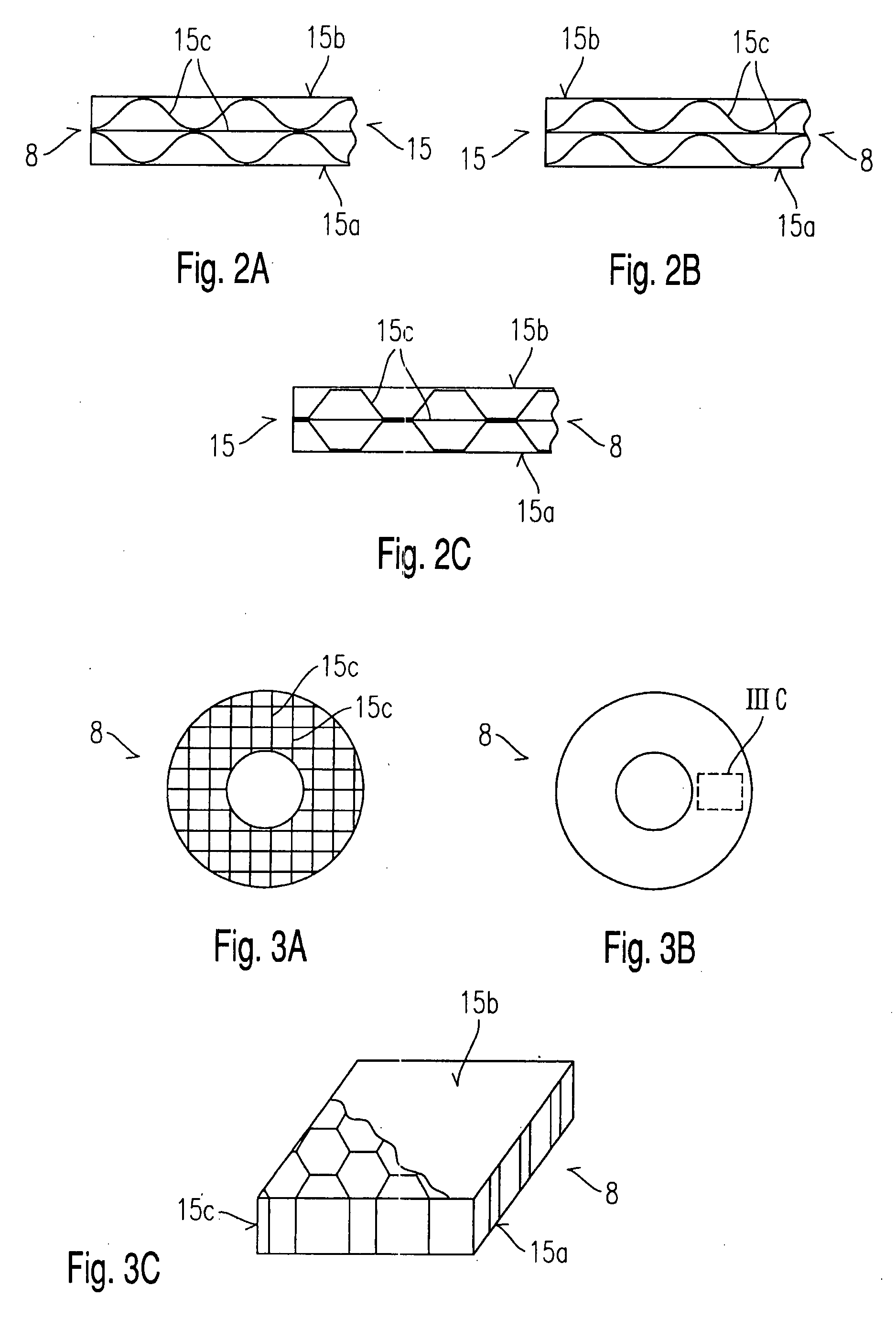
[0004]In contrast, the intermediate element for a fuel injector according to the present invention, having the characterizing features of the main claim, has the advantage that a suitable design of an intermediate element between the fuel injector and the cylinder head and / or between the fuel injector and a pinning-down clamping shoe, or a spring element, effects a decoupling of the fuel injector, which reduces the transmission of structure-borne noise to other components of the internal combustion engine. The intermediate element has a plurality of layers, i.e., at least three layers, which have different forms and / or are made of different materials.
[0006]In particular, it is advantageous that the number of intermediate layers is variable and adaptable to the given situation.
[0008]The patterns of adjacent layers may be arranged in an in-phase manner, in phase opposition or rotated with respect to each other in order to allow only point-wise contact of adjacent layers so as to dampen the structure-borne noise in this manner.
[0009]The layers may be implemented by different methods during the manufacturing process, by soldering, welding, crimping, clamping or compressing, for instance. A cup-shaped design of the bottom layer facilitates the connection.
[0011]The cavities between the intermediate layers may be provided with suitable fillers such as metal shavings or balls of materials such as metal, plastic, or mineral balls in order to dampen the structure-borne noise even further.

Problems solved by technology

A particular disadvantage of known annular washers is that, although the positioning of the fuel injector in the cylinder head is able to be corrected, the solid design of the annular washer made of wire, copper, steel or similar materials creates a structure-borne noise bridge between the fuel injector and the cylinder head.
This transmits the structure-borne noise, which is generated in the fuel injector by the switching pulses, to other components of the internal combustion engine and generates annoying noise.

Method used


Image

  • Intermediate Element for a Fuel Injector
  • Intermediate Element for a Fuel Injector
  • Intermediate Element for a Fuel Injector

Examples


Embodiment Construction

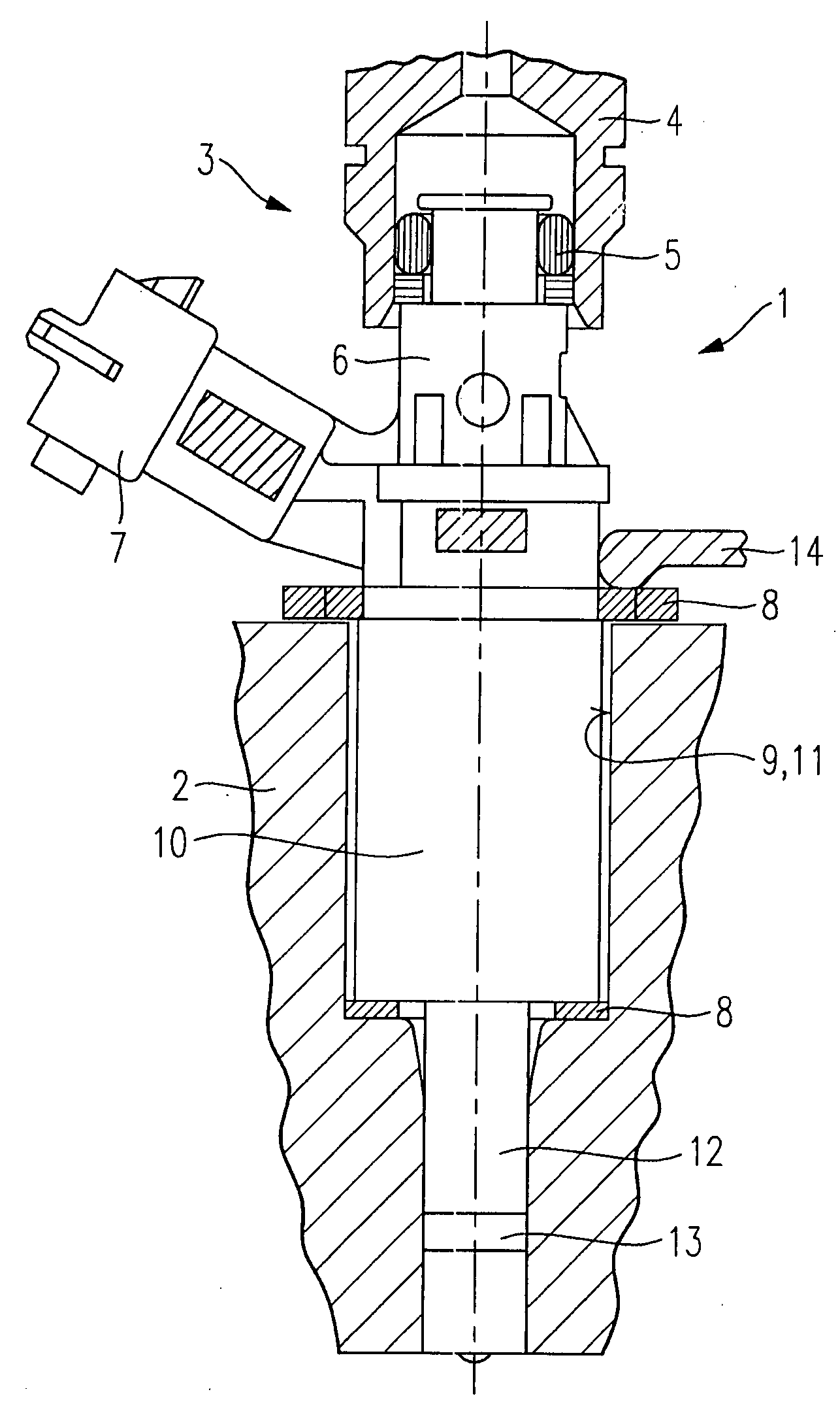
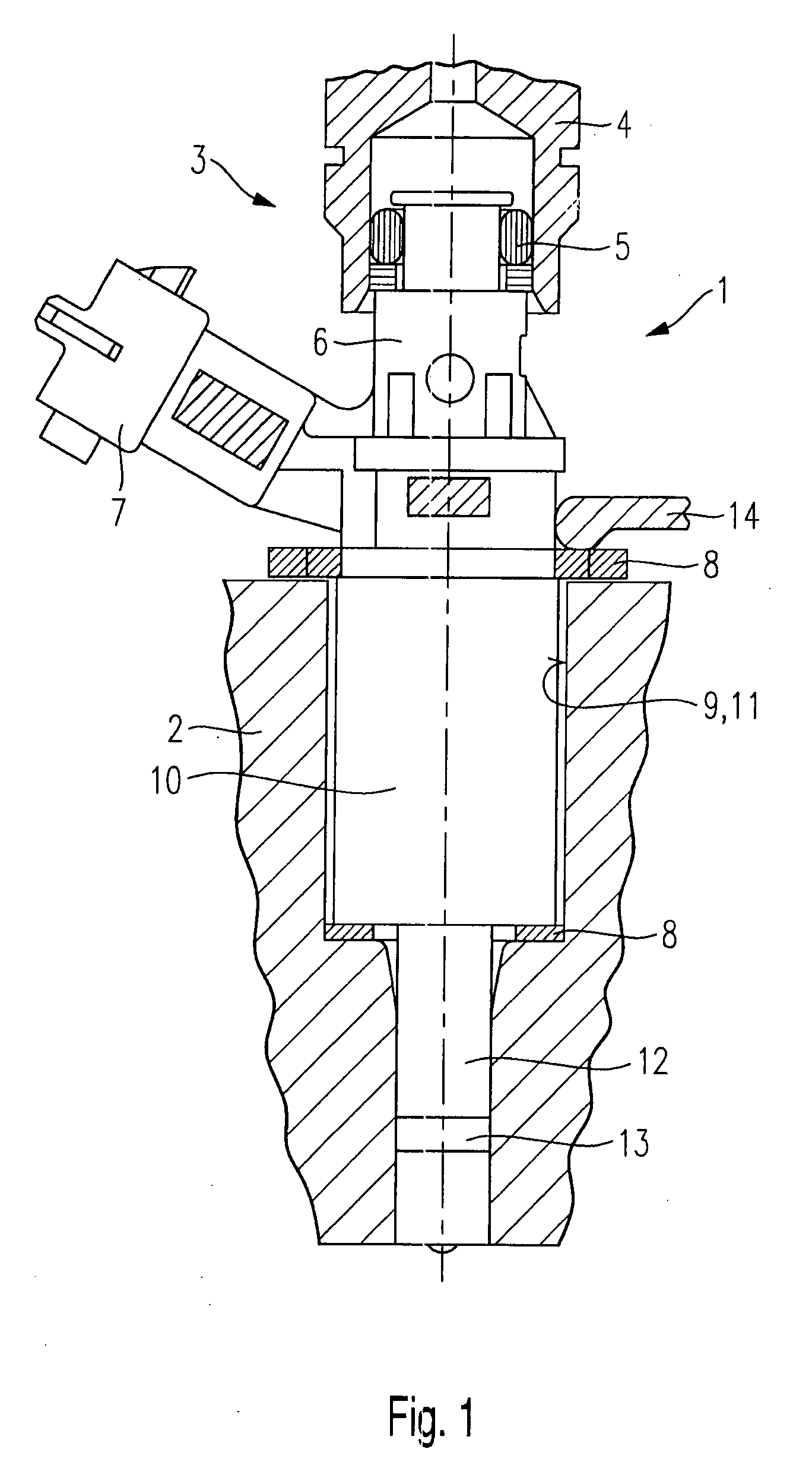
[0021]FIG. 1 shows a schematized part-sectional view through an exemplary embodiment of a fuel injector 1 equipped with an intermediate element 8 according to the present invention, in a receiving bore of a cylinder head of a mixture-compressing internal combustion engine having externally supplied ignition.

[0022]Here, a fuel injector 1 is designed as a directly injecting fuel injector 1 and installed in a cylinder head 2 of an internal combustion engine. At an end 3 on the intake side, fuel injector 1 is provided with a plug connection to a fuel-distributor line 4, which is sealed by a seal 5 between fuel-distributor line 4 and a supply connection 6 of fuel injector 1. Fuel injector 1 has an electrical connection 7 for the electrical contacting in order to actuate fuel injector 1.

[0023]According to the present invention, fuel injector 1 has an intermediate element 8 in receiving bore 9 of cylinder head 2, between a wall 11 of receiving bore 9 and a valve housing 10 of fuel injector...


PUM


Abstract

An intermediate element for a fuel injector situated in a cylinder head of an internal combustion engine is disposed between a valve housing of the fuel injector and a wall of a receiving bore of the cylinder head, and / or between the valve housing and a clamping shoe holding the fuel injector down in the cylinder head. The intermediate element is made up of a plurality of layers having different patterning and / or being made of different materials.

Description

RELATED ART[0001]The present invention is based on an intermediate element for a fuel injector of the type set forth in the main claim.[0002]From DE 101 08 466 A1, for instance, an intermediate element for supporting a fuel injector in a cylinder head of an internal combustion engine is known. The intermediate element is in the form of an annular washer and situated between a valve housing of the fuel injector and a wall of a receiving bore of the cylinder head. The annular washer has a round or oval cross section, and a shoulder of the valve housing is set apart from a shoulder of the cylinder head by the annular washer.[0003]A particular disadvantage of known annular washers is that, although the positioning of the fuel injector in the cylinder head is able to be corrected, the solid design of the annular washer made of wire, copper, steel or similar materials creates a structure-borne noise bridge between the fuel injector and the cylinder head. This transmits the structure-borne...

Claims


Application Information

Patent Timeline
IPC IPC(8): F02M61/14
CPCF02M61/14F02M2200/09F02M61/166
Inventor LISKOW, UWE
Owner ROBERT BOSCH GMBH
Learn More