Tube system for ventilation appliances

Active Publication Date: 2009-02-26
HAMILTON MEDICAL AG
View PDF14 Cites 70 Cited by
  • Summary
  • Abstract
  • Description
  • Claims
  • Application Information

AI Technical Summary

Benefits of technology

[0023]For the mechanical ventilation of a patient using a ventilation appliance suitable for invasive ventilation, the breathing frequency, the breathing pressure, the endexspiratory pressure, and the breathing volume are monitored in a known manner using a flow sensor on the patient side. Due to the parameters detected by the flow sensor, and by using the gas mixer, the inhalation valve, and the exhalation valve, the breathing pressure, the breathing volume, and the endexspiratory pressure are controlled in a patient-oriented manner. Any leakages possibly present are compensated, in that the gas mixer, the in

Problems solved by technology

Until now it was deemed impossible to connect one tube of

Method used


Image

  • Tube system for ventilation appliances
  • Tube system for ventilation appliances
  • Tube system for ventilation appliances

Examples


Embodiment Construction

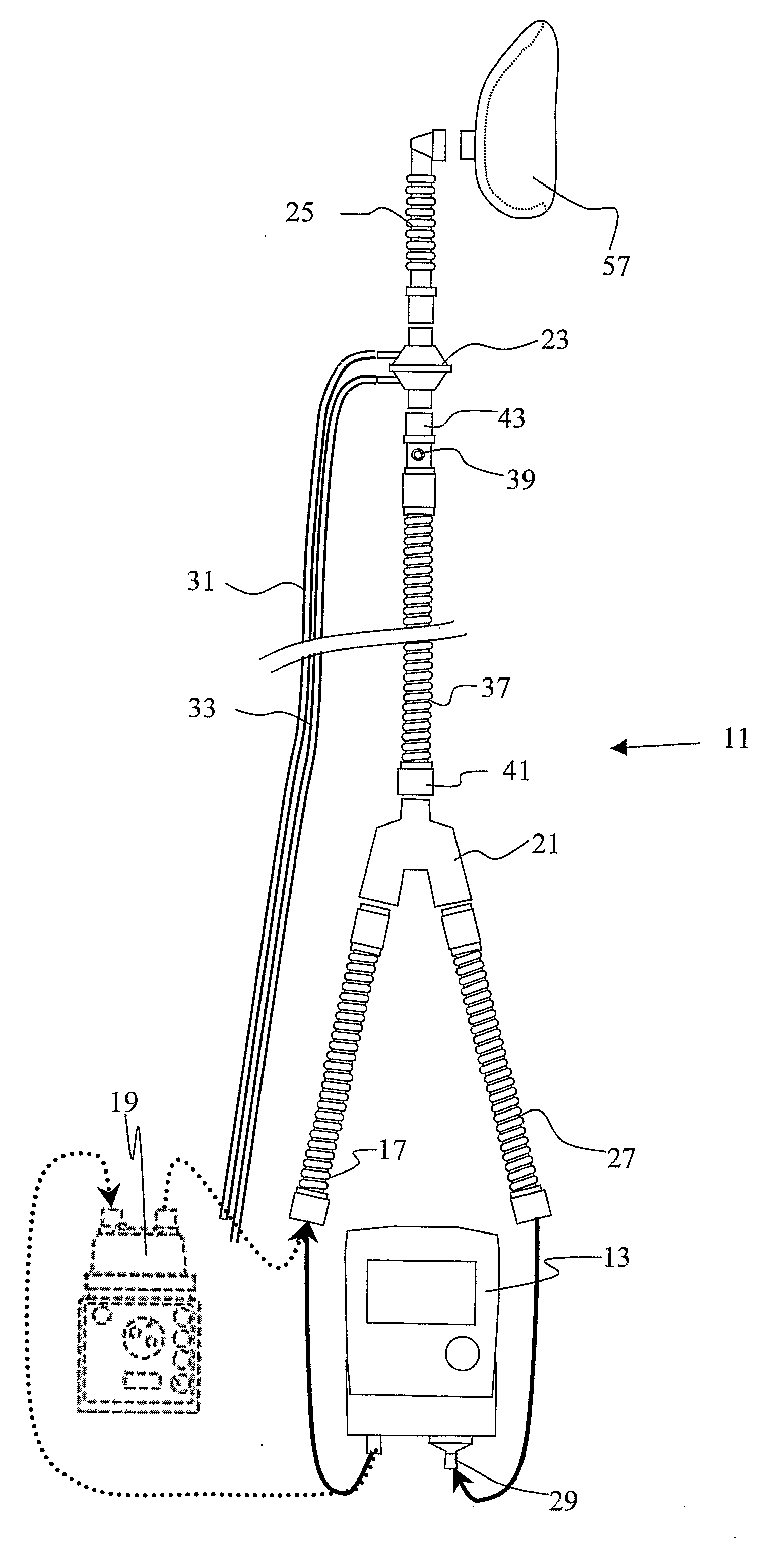
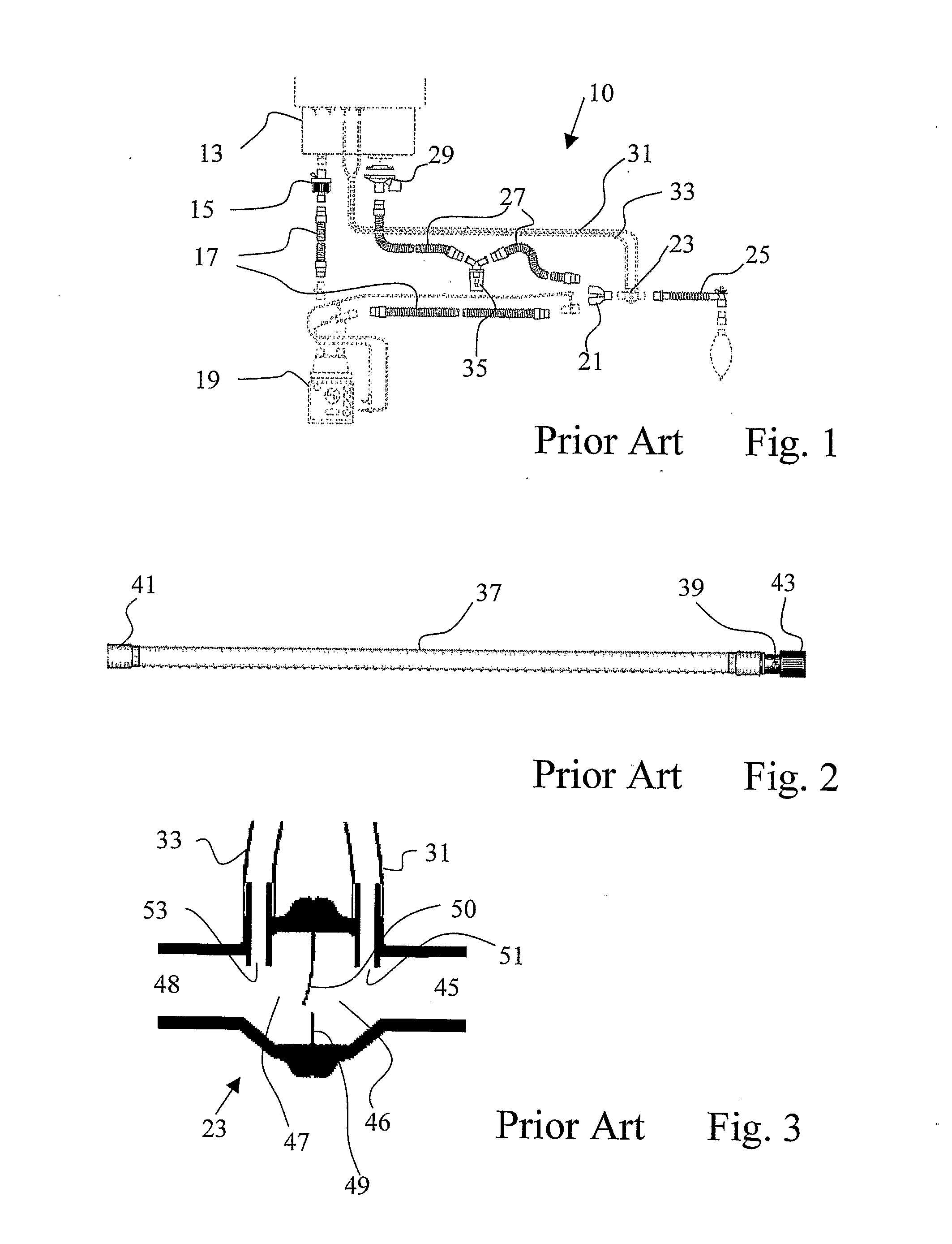
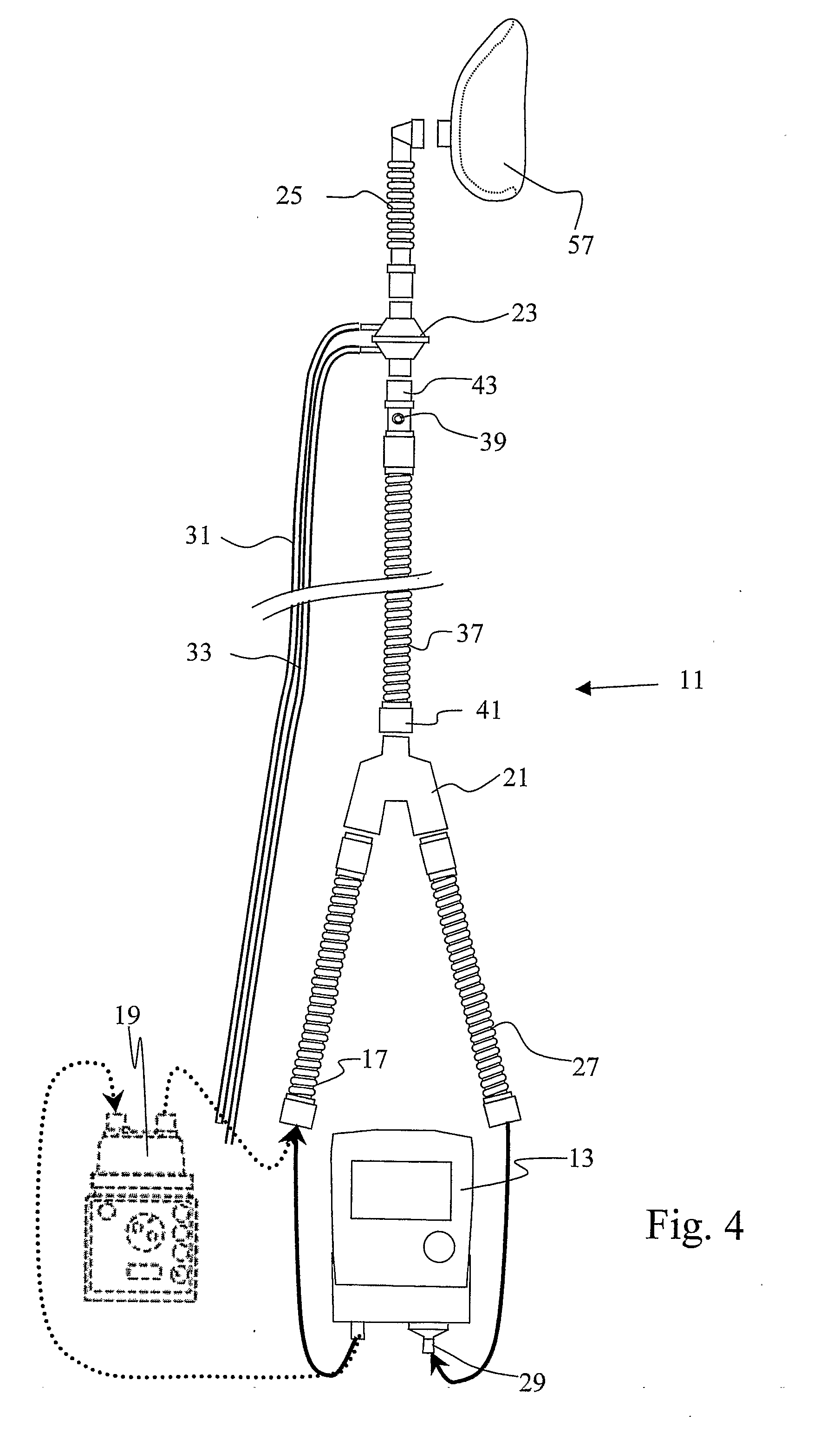
[0032]FIG. 4 illustrates the tube system 11 according to the invention. The components are known. The composition, however, is novel, and has critical advantages. The inhalation tube 17 and the exhalation tube 27 are short pieces of tubes, such as are used, for example, in the tube system 10 according to FIG. 1 between the filter 15 and the moisturizing device 19. Their length must simply allow that both tubes can be connected at their one ends to the ventilation appliance. A moisturizing device 19 may also be provided in this area between the ventilation appliance 13 and the Y piece. The Y piece, which gathers the two tubes 1727 on the appliance side and combines them with the ventilation tube 37, may be identical to the previously known Y piece. The ventilation tube 37 connected to the same is a tube according to FIG. 2, and is also known. The flow sensor 23, which is arranged on the ventilation tube 37 on the patient side, is also known. The composition according to the invention...


PUM


Abstract

The invention relates to a three-arm tube system (11) for a ventilation appliance (13) suitable for invasive ventilation. Such a ventilation appliance comprises an active inhalation valve and an active exhalation valve (29). The tube system (11) comprises an inhalation tube arm (17), an exhalation tube arm (27) and a ventilation tube arm (37) for attachment to a mask (57), and also a flow sensor (23). According to the invention, a defined leakage (39) is established in the ventilation tube (37), and the flow sensor (23) is arranged between leakage (39) and mask (57). The invention further relates to a ventilation appliance having such a tube system, and to a method for operating a ventilation appliance.

Description

SCOPE OF THE INVENTION[0001]The invention relates to a tube system for ventilation appliances, a ventilation appliance having such a tube system, a method for operating a ventilation appliance, and a method for the mechanical ventilation of patients.PRIOR ART[0002]Dual tube systems are utilized for invasive ventilation. Dual tube systems have an inhalation tube and an exhalation tube that are connected to the patient mask via a Y piece. The inhalation tube is subsequently connected to an inhalation filter protecting the ventilation appliance from contamination. A moisturizing device is possibly arranged between an inhalation tube piece on the device side and an inhalation tube piece on the patient side. On the patient side of the Y piece a flow sensor may be arranged, and a tubus via an intermediate tube.[0003]The exhalation tube connecting the Y piece feeds the breathing air back to the ventilation appliance, and may be equipped with a water trap. The ventilation appliance has an i...

Claims


Application Information

Patent Timeline
IPC IPC(8): A61M16/00
CPCA61M16/0051A61M16/06A61M16/08A61M16/16A61M16/205A61M2205/15A61M16/0833A61M16/204A61M2016/0036A61M16/107A61M16/024
Inventor BRUNNER, JOSEF
Owner HAMILTON MEDICAL AG
Why Eureka
Try Eureka